Continue to Site

Welcome to EDAboard.com

Welcome to our site! EDAboard.com is an international Electronics Discussion Forum focused on EDA software, circuits, schematics, books, theory, papers, asic, pld, 8051, DSP, Network, RF, Analog Design, PCB, Service Manuals... and a whole lot more! To participate you need to register. Registration is free. Click here to register now.

envelope dectector vs Product modulator

Status
Not open for further replies.

iVenky

Advanced Member level 2
Joined
Jul 11, 2011
Messages
584
Helped
37
Reputation
76
Reaction score
35
Trophy points
1,318
Location
College Station, Texas
Activity points
6,124
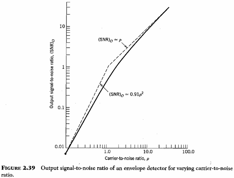
In AM receiver I read that if the SNR is very less then product modulator is better compared to envelope dectector. Why is that so?

Thanks a lot.
 

Modulator usually located on transmitter side. It cannot be better for AM receiver.

I guess the following: Envelope detection is related to usual DSB-AM signal. In best case with modulation index m=1 only half of the transmitted energy is spent on the signal itself, the other half is spent on transmission of the carrier, which is unuseful.

But product modulator is related to DSB-AM-SC - with suppressed carrier. So the whole your transmitter power is spent on useful data transmission which is better in presence of heavy noises.
 

In simple words, synchronous demodulation supresses the signal components orthogonal to the carrier, resulting in a 3 dB SNR improvement, presumed you can perfectly lock to the carrier.
 

At high SNR there is no difference between the two. At near 1:1 SNR the envelope detector is 6 dB worse. One main advantage of the product one is that leakage from adjacent channels are at a frequency higher than the audio on the desired channel and can be eliminated with a low pass filter in the following audio stages.
 

In simple words, synchronous demodulation supresses the signal components orthogonal to the carrier, resulting in a 3 dB SNR improvement, presumed you can perfectly lock to the carrier.

I understand that it supresses the signal components that are orthogonal to it but how do you say that it is 3db?

- - - Updated - - -

At high SNR there is no difference between the two. At near 1:1 SNR the envelope detector is 6 dB worse. One main advantage of the product one is that leakage from adjacent channels are at a frequency higher than the audio on the desired channel and can be eliminated with a low pass filter in the following audio stages.

I had one doubt already in envelope detector. Here's the doubt. Basically if you want to demodulate you have to down-convert it and pass it through a low pass filter. Envelope detector demodulates the signal but it doesn't down-convert it at all
 

how do you say that it is 3db
Noise can be split into two orthogonal components, as any othogonal or uncorrelated signals they add by their power rather than magnitude.
 

In simple words, synchronous demodulation supresses the signal components orthogonal to the carrier, resulting in a 3 dB SNR improvement, presumed you can perfectly lock to the carrier.

This is not right. Whilst it is correct in that the synchronous demodulator suppresses the noise in the quadrature channel, which is half the noise, the effect of noise on the envelope detector is much more complex.

The envelope detector is always worse, but rarely by 3dB.

In high S/N situations (e.g. consumer AM radio) the two systems perform much the same. This is because the non-linear envelope detector under high S/N only really responds to noise in the in-phase channel (the amplitude noise) and not the quadrature channel (essentially the phase noise).

In the other extreme where the signal level is much less than the noise level, the noise captures the envelope and it is hard to define any sort of meaningful S/N ratio. Here the envelope detector is much worse than the product detector, by greater than 3dB.

For a starting analysis look in Proakis and Salehi "Communication System Engineering" p220-225
 
  • Like
Reactions: FvM

    FvM

    Points: 2
    Helpful Answer Positive Rating
This is not right. Whilst it is correct in that the synchronous demodulator suppresses the noise in the quadrature channel, which is half the noise, the effect of noise on the envelope detector is much more complex.

The envelope detector is always worse, but rarely by 3dB.

In high S/N situations (e.g. consumer AM radio) the two systems perform much the same. This is because the non-linear envelope detector under high S/N only really responds to noise in the in-phase channel (the amplitude noise) and not the quadrature channel (essentially the phase noise).

In the other extreme where the signal level is much less than the noise level, the noise captures the envelope and it is hard to define any sort of meaningful S/N ratio. Here the envelope detector is much worse than the product detector, by greater than 3dB.

For a starting analysis look in Proakis and Salehi "Communication System Engineering" p220-225
For a peak detecting envelope detector, the actual output SNR might not always be different by 3dB. But the input-referred SNR will be 3dB better with coherent demodulation.
 
  • Like
Reactions: FvM

    FvM

    Points: 2
    Helpful Answer Positive Rating
The envelope detector is always worse, but rarely by 3dB.
I didn't apply to retell the theory of envelope detectors.

You are able to define a demodulator model where the 3 dB property is achieved. If it's representative for typical receivers is a different system. According to my experience, the 3 dB assumption is fairly valid for real world demodulation of smallband signals. I'm able to reproduce it in measurements.

Referring to mtwieg's comment, in a small band demodulator, the envelope detector does not work as a peak detector.

P.S.: A peak amplitude evaluating envelope detector correlates both quadrature components, so I agree that the SNR difference can be any value between 0 and 6 dB for it.
 
Last edited:

You are able to define a demodulator model where the 3 dB property is achieved. If it's representative for typical receivers is a different system. According to my experience, the 3 dB assumption is fairly valid for real world demodulation of smallband signals. I'm able to reproduce it in measurements.

At the risk of doing the OP's homework, this is not true - see the following figure from Lathai "Modern Digital and Analog Communication Systems"

lathai1.jpg

P.S.: A peak amplitude evaluating envelope detector correlates both quadrature components, so I agree that the SNR difference can be any value between 0 and 6 dB for it.

The S/N degradation approaches 0dB as the input S/N becomes very large, but for small (negative) S/N it is unbounded, and becomes much greater than 6dB.

I think the reason this is somewhat non-intuitive (apart from the fact that noone teaches anything about DSB AM these days) is that the envelope detector is non-linear, and that in the large S/N case it effectively splits the noise into two non-stationary components (AM noise and PM noise) and rejects the PM noise. This is how it is able to achieve much the same performance as the coherent case - the phase noise is essentially the noise in the quadrature channel rejected by the synchronous detector. A similar effect occurs when only half of any additive stationary noise to a carrier contributes to phase noise.
 
Last edited:
  • Like
Reactions: FvM

    FvM

    Points: 2
    Helpful Answer Positive Rating
The near 0 dB case is almost obvious, but the > 6 dB isn't at first sight. I assume that additional assumptions about the signal and noise characteristic must be made.

Thanks for the explanation.
 

Hi all,

I point out two aspects of the envelope AM detection.


A] A phasorial picture helps to see the effect. Think in an ideal envelope detector (regardless of diodes or circuits, but a mathematical model):
At high SNR, the quatrature component of noise practically does not change the modulus of the phasor. The variations in ampitude follow the in-phase component of the noise, that is assumed gaussian.
Al very low SNR, the amplitude depends of both the in-phase and quadrature noise components (and very few of the signal) and it is no more gaussian. (It is Rayleigh distributed if signal is wery weak.)


B] From another point of view, let's consider an imaginary experiment in several steps made with "real" circuits.

1) Imagine that a synchronous demodulator (using a mixer of the diode-ring type) is used for detection of AM.
The local oscillator (LO) of exactly the same frequency of the carrier and in phase with it is applied to the LO port of the mixer, and the modulated signal is applied to the other. The diodes act like switches controlled by the LO: the LO decides which branches conduct. The behaviour is that of a synchronous detector, i.e., SNR at the demodulated signal follows SNR at the input (1 dB variation in SNR_in gives 1 dB variation at SNR_out). The demodulator is linear. (Later, a low-pass filter leaves only the baseband demodulated signal.)

2) Now, imagine a detector made with a single diode loaded with an R at the output (no C filter; a low-pass filter can be added later). The sum LO+modulated_signal voltage is applied to it, and assume that the LO has a level much higher than the signal. The result is essentially the same: there is now a single switch that conducts or not, driven by the LO.

3) Now, remove the LO, i.e., apply only the AM signal (without noise). The conduction of the diode is controlled by the carrier (the amplitude modulation does not change the zero crossings of the signal). The signal itself does the job that in 2) was done by the LO.

4) The same as in 3), but increasing noise, i.e. decreasing SNR. The noise starts to be contribute to "decide" when the diode conducts and when it doesn't. More precisely, we should say that the quadrature component of the noise changes the zero-crossings of the RF (or IF) signal.
At very low SNR, noise "takes control" of the switch (the diode), deciding when it conducts. In that condition, 1 dB variation in SNR_in gives 2 dB variation at SNR_out, as shown in the following figure, very similar to that of Fred23:


The behaviour of "real" circuits in B] are (approximately) described by the model in A].

Regards

Z
 
Last edited:
  • Like
Reactions: fred23

    fred23

    Points: 2
    Helpful Answer Positive Rating
Status
Not open for further replies.

Part and Inventory Search

Welcome to EDABoard.com

Sponsor

Back
Top