rsashwinkumar
Member level 4
Hi all,
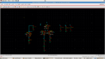
I was designing a current-cell for a current steering DAC, I used a differential switch topology with a single MOS current source, biased at 10uA. I have attached the schematic. When i tried estimating the output impedance, i got an impedance of 361 Mohm, which I think too high. The way i tested the output impedance was to inject a test source of 1 A AC magnitude and measured the voltage at that node. Is that okay or is there something else i am missing here...
Plz help me out..,.