djnik1362
Full Member level 2
hi
I need to re-design a RF circuit with new technologies.
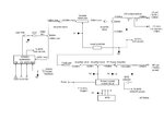
The old design was done in 20 years ago and this is the block diagram of the old circuit :

This circuit intent to do these jobs :
1 - Produce a CW RF output with +3dbm power.
2 - Produce a Pulsed RF output with rectangular shape with 10us pulse width +25dbm power.
3 - Produce a CW RF output with -7dbm power for monitoring.
The old designed circuit had a BIT (Built in Test) section to check internal operation and
in new design it must be included. The circuit must operate in frequency range about
900MHz to 1.3GHz and synthesizer can be tuned externally with 1MHz step in this range.
So with this information i need some idea for re-design this circuit
with new technologies and with new approaches.I prefer to use a real-time
and smart tuning circuits in new design. Performance and stability of this circuit
is very important.
I am new in RF design but have 6 years experience in Electronic Design
(Analog , Microcontrollers, FPGA) and Signal Processing.
Thanks for your support.
I need to re-design a RF circuit with new technologies.
The old design was done in 20 years ago and this is the block diagram of the old circuit :

This circuit intent to do these jobs :
1 - Produce a CW RF output with +3dbm power.
2 - Produce a Pulsed RF output with rectangular shape with 10us pulse width +25dbm power.
3 - Produce a CW RF output with -7dbm power for monitoring.
The old designed circuit had a BIT (Built in Test) section to check internal operation and
in new design it must be included. The circuit must operate in frequency range about
900MHz to 1.3GHz and synthesizer can be tuned externally with 1MHz step in this range.
So with this information i need some idea for re-design this circuit
with new technologies and with new approaches.I prefer to use a real-time
and smart tuning circuits in new design. Performance and stability of this circuit
is very important.
I am new in RF design but have 6 years experience in Electronic Design
(Analog , Microcontrollers, FPGA) and Signal Processing.
Thanks for your support.