Continue to Site

Welcome to EDAboard.com

Welcome to our site! EDAboard.com is an international Electronics Discussion Forum focused on EDA software, circuits, schematics, books, theory, papers, asic, pld, 8051, DSP, Network, RF, Analog Design, PCB, Service Manuals... and a whole lot more! To participate you need to register. Registration is free. Click here to register now.

startup citcuit for self bias

Status
Not open for further replies.

analog_ambi

Member level 1
Joined
Jul 19, 2011
Messages
39
Helped
1
Reputation
2
Reaction score
1
Trophy points
1,288
Activity points
1,560
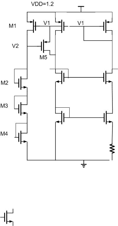
M1-M5 constitute startup circuit for the self bias refernce. VDD is 1.2 and V1 is usuall 700mV. M1 is sized for current=30nA.

After circuit startsup V2 is 1v and M1 goes to triode, M5 turns off. Is M1 going to triode after startup a problem?

48_1343894046.jpg
 

As long as M5 leakage is negligible and you can afford to throw away the current flowing in the first branch then you are fine. You might be better off dropping another 300mV on V2 to make the gate of M5 closer to its source...
 

Make sure your start up circuit actually does its job correctly (e.g. using a slow start up ramp for VDD): as there's no control for the startUp circuit, it could be possible that M5 stays always off (and so doesn't work as startUp).
 

Make sure your start up circuit actually does its job correctly (e.g. using a slow start up ramp for VDD): as there's no control for the startUp circuit, it could be possible that M5 stays always off (and so doesn't work as startUp).
Hi erikl

this circuit is commonly used e.g. see Baker's CMOS book; there are only a couple of things that can go wrong: it does not turn off properly or it generates more than one OP.

Startup is guaranteed because during power ramping in absence of bias current V1 tracks vdd while V2 and M5:D track vss
 

Make sure your start up circuit actually does its job correctly (e.g. using a slow start up ramp for VDD):).

By slow ramp how much rise time do you mean? I have checked for 1 us rise time. It works excellent! I made 0 current initial condition so that PMOS and NMOS are off.

- - - Updated - - -

You might be better off dropping another 300mV on V2 to make the gate of M5 closer to its source...

The gate leakage under reverse bias i.e. Vgs=300mV (positive) for PMOS is atto amps. So, its negligible. You are asking me to make Vgs=0 so as to reduce this leakage..right?
 

Using a negative Vsg in a PMOS will in general increase leakage wrt Vsg =0 because of GIDL. This is very technology dependent and not always modeled; since I do not know what kind of process and specs you are dealing with, it is worth mentioning. Furthermore in your case Vsg5=0 would keep M1 in saturation and reduce your wasted current
 
Last edited:

I agree with erikl. If there is current leakage for M1, possibly V2 voltage might be too high and turn off M5 always.
 

I agree with erikl. If there is current leakage for M1, possibly V2 voltage might be too high and turn off M5 always.

according to the opening post, M1 is sized for 30nA, it's a long PFET (as required by this design) where do you see leakage coming from? gate leakage for a 1.2V oxide with Vsg=0 is completely negligible...
 
Last edited:

Using a negative Vsg in a PMOS will in general increase leakage wrt Vsg =0 because of GIDL. This is very technology dependent and not always modeled; since I do not know what kind of process and specs you are dealing with, it is worth mentioning. Furthermore in your case Vsg5=0 would keep M1 in saturation and reduce your wasted current

I am using IBM130 cmrf8sf. This circuit is a part of temperature sensor with range -20 to 30C. So I dont want to keep Vsg close to 0. Even small current through M5 due to small positive Vsg will cause imbalance in the self bias circuit and cause error in temperature reading.

I did not understand how keeping M1 in saturation will reduce waste current. In triode the current will be less or equal to that of saturation..right?
 

By slow ramp how much rise time do you mean? I have checked for 1 us rise time. It works excellent! I made 0 current initial condition so that PMOS and NMOS are off.

That's good. But I'd also try with a much longer rise time in the order of 100ms (imagine a mains adapter loading a huge capacitor).
 
I am using IBM130 cmrf8sf. This circuit is a part of temperature sensor with range -20 to 30C. So I dont want to keep Vsg close to 0. Even small current through M5 due to small positive Vsg will cause imbalance in the self bias circuit and cause error in temperature reading.

I did not understand how keeping M1 in saturation will reduce waste current. In triode the current will be less or equal to that of saturation..right?

In cmrf8sf GIDL won't be a problem.

As of the second point, the current through M1 will go up or down depending on how you move it back into saturation:
- if you resize M1, moving it back into saturation means the voltage on top of the 3 diode connected NFETs went down hence the branch current went down
- if you resize or change the NFET diodes keeping M1 the same then you are right since you operate at constant Vg you just follow the Vds vs Id chracteristic

Thank you so much for your intuitive analysis!

- - - Updated - - -

Thank you erikl for the info!
 

Status
Not open for further replies.

Part and Inventory Search

Welcome to EDABoard.com

Sponsor

Back
Top