Continue to Site

Welcome to EDAboard.com

Welcome to our site! EDAboard.com is an international Electronics Discussion Forum focused on EDA software, circuits, schematics, books, theory, papers, asic, pld, 8051, DSP, Network, RF, Analog Design, PCB, Service Manuals... and a whole lot more! To participate you need to register. Registration is free. Click here to register now.

SD card to PIC controller

Status
Not open for further replies.

stoyanoff

Full Member level 4
Joined
Aug 10, 2011
Messages
195
Helped
8
Reputation
16
Reaction score
8
Trophy points
1,298
Activity points
2,725
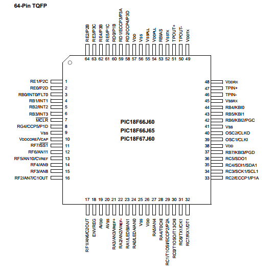
Hi! I want to connect 18F66J60(3.3V Vcc) to SD card.
I want to be sure my chart is OK. So here are the connections:
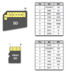
PIN 1 of the SD card is connected to PIN 33(RC2/CS) of the 18F66J60
PIN 2 ----- --- to PIN 36(RC5/SDO)
PIN 3 ---- --- to GRD
PIN 4 ---- ---- to Vcc
PIN 5 ---- --- to PIN 34(RC3/SCK)
PIN 6 ---- ---- to GRD
PIN 7 ---- ---- to PIN 35(RC4/SDI)
PIN 8 and 9 through pull-up resistor(10k) to Vcc
PINs 1,2,5,7 have pull-up resistors, too.
Is everything OK??
 

Have a look at the schematic below:-

SD Card.PNG

If your controller operates on 3.3 V then there is no need to use the voltage divided and if it works on 5V then you have to put that voltage divided in between the SD Card and Controller and also make sure that, Voltage on SD Card doesn't exceed the 3.3V because it can damage your card.
 

OK! My controller is running on 3.3V. Do I need pull-up or pull-down resistors on the comunication pins???
 

OK! My controller is running on 3.3V. Do I need pull-up or pull-down resistors on the comunication pins???

No it is not required....
In SPI communication, there is no need for pull ups..
While in I2C you need pull ups..
 

I have this book.
First I tried to work with the card with CCS complier program - without any success. So I switch to mplab C18 and I`m following this book. I can`t adjust the standard demo to work with my controller. I`m following the steps from the book, but ....
I want to be sure, my hardware is OK and to start looking for the error in the program.
 

In SD mode, pull-up resistors are assumed because all communication lines are bidirectional. In SPI mode, you can omit pull-ups for lines, that are permanently driven from the host.

The SD card specification say explicitely that reserved lines (unused communication lines) should be connected to pull-uo resistors in SPI mode. Ignoring this point can cause excessive current consumption, but unlikely communication failure.
 

Hello,

Since you have 9 pins on SD card you don't use microSD card. If you use this PIC:


than you done job good. Dont forget to put some filter capacitors. You don't need any pull-ups.
 

Attachments

  • pic18F66J60.PNG
    pic18F66J60.PNG
    57.2 KB · Views: 90
  • sd-card-pinout.png
    sd-card-pinout.png
    58.5 KB · Views: 85
Last edited by a moderator:

Status
Not open for further replies.

Part and Inventory Search

Welcome to EDABoard.com

Sponsor

Back
Top