Continue to Site

Welcome to EDAboard.com

Welcome to our site! EDAboard.com is an international Electronics Discussion Forum focused on EDA software, circuits, schematics, books, theory, papers, asic, pld, 8051, DSP, Network, RF, Analog Design, PCB, Service Manuals... and a whole lot more! To participate you need to register. Registration is free. Click here to register now.

LM139APT- Comparator issues above -20°C

Status
Not open for further replies.

anandss

Newbie
Joined
Jul 11, 2012
Messages
4
Helped
0
Reputation
0
Reaction score
0
Trophy points
1,281
Activity points
1,445
Hi,

I have observed the following problems during our thermal cycle testing on our Hardware.

1.The comparator we are using is LM139APT with operating temperature from -55°C to +125°C, and TSSOP LM139APT_schematic.JPG.We are using for the Over-voltage monitoring for different voltages.
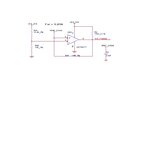
The ckt description is as given below:
a.To the inverting input pins the monitoring voltages (3V3,5V,15V,-15V) are connected through resistor divider.
b.To the Non-inverting pins ,we have connected Vref voltage of 2.048V derived from the ADR440BRZ IC.
c. VCC+ pin 3 is 3V3
VCC - Pin 12 is GND
d.Pin 1,2,14,13 pulled high 100k res to 3.3 voltage
e.And feedback resistor of 10M from all o/p pins to the non-inverting input pins.

For normal voltages the output of the comparator will be High(3V3),and for overvoltages it will be Low(0V)

We have stable input voltages 3V3,5V,15V,-15V at the Inverting input pins at operating temperature from -40°C to +75°C,
But we are seeing that the comparator is not working properly(always low) above -20°C.
As mentioned the monitoring voltages(3.3V,5V,15V,-15V) are stable

Also schematics are attached.
So what may be the possible reasons for the comparator not working above -20°C?
 

Look at the LM139's datasheet. Under Electrical Characteristics, 4th item:

Input Common-Mode Voltage Range ... 0 to Vcc-1.5 V

You are powering the device with 3.3V, and expecting it to compare two voltages around 2V. Thus, the input common-mode voltage for your circuit is Vcc-1.3V; this is outside the specified operating range.

You should attach a voltage divider to the reference, so that instead of comparing with 2.048V, you are comparing with 1.024V. (Remember to adjust the monitoring voltage resistor dividers appropriately!)

Hope this helps!
 
Thanks for your reply....!!!

The comparator is working fine at ambient temperature and also from temperature range 70°C to -20°C.But
Temperature above -20°C its not working properly i.e comparator output will be always low(comparator o/p pin is given to CPLD pin).

1.Is there any issues with INput bias current of the opamp in comparator at lower negative temp?
2.Any issues with the 100k pull up and 10M ohm feedback resistor?(whether the comparator is not able to drive the CPLD pin CL=8pf for CPLD)


Regards,
Anand
 

The comparator is working fine at ambient temperature and also from temperature range 70°C to -20°C.But
Temperature above -20°C its not working properly i.e comparator output will be always low(comparator o/p pin is given to CPLD pin).

Note: What you mean to say, is that it's not working properly for temperatures BELOW -20°C. (70 is above -20.)

1.Is there any issues with INput bias current of the opamp in comparator at lower negative temp?

As temperature goes down, the allowable range for input common-mode decreases: the mandatory difference between Vcc and the common-mode inputs must increase.

For example, even though it might run fine when the inputs are Vcc-1V at 55°C, it'll need Vcc-1.1V at 30°C and Vcc-1.3V at -20°C.

This is because the input stage to the comparator is made up of darlington PNP transistors (the datasheet has a Schematic Diagram showing the internal circuitry). The input must be at least 2 VBE below the positive rail (plus VCESAT). As temperature decreases, VBE increases at about ~2mV/°C (this reflects the fundamental behavior of diodes). So, as temperature goes down, you get ~4mV less range per °C. If the inputs to the comparator are both above the allowable common-mode range, the input stage transistors TURN OFF. The input bias current will go to zero, and the comparator output will be dictated by internal leakage currents within the op-amp. (i.e., the output will be uncontrolled.) This is very undesirable!

To avoid this, you should not operate the comparator outside of its specified operating range. In fact, you should give it margin. If you divide the reference down to 1V instead of 2V, then you will have 0.7V of margin from the datasheet specification. This is desirable.

The alternative is to power the comparator from 5V instead of 3.3V. 5V-2.048V provides plenty of margin from the datasheet spec.

When the comparator is run within specifications, there is no issue with input bias current at different temperatures.

2.Any issues with the 100k pull up and 10M ohm feedback resistor?(whether the comparator is not able to drive the CPLD pin CL=8pf for CPLD)

The 100k is fine, and driving 8pF will be fine. I don't see, however, why the 10MΩ resistor is included; it isn't doing anything.

Hope this helps!
 
I agree that your temperature problems are likely from using the device outside its common-mode ratings. You can't expect a circuit to work properly if you don't use it within its limits. :wink:
 

Thanks for ur reply zeker.......!!!it helped me a lot
 

The alternative is to power the comparator from 5V instead of 3.3V. 5V-2.048V provides plenty of margin from the datasheet spec.

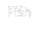
Hi,I have connected the comparator power supply to 5V instead of 3.3V,but @-30°C,we are seeing the comparator output toggling (now we have given a Vcm=3v according to the datsheet)
I have attached the circuit diagram also.LM139APT_schematic1.JPG

What may be the problem.....!!!!
 

What do you mean by "toggling"? Do you mean the output continuously jumps up and down? If so, does it happen when the output should be low or when it should be high, or only when the input is close to the reference voltage?

If the output is unstable when the input is close to the threshold, it may help to add some positive feedback to give hysteresis. The 10M resistor in the circuit looks like it is intended to give positive feedback. However that won't work as pin 5 is connected directly to the low impedance voltage reference. The circuit may work better with a resistor (say 10K) between pin 5 and the voltage reference.
 

Status
Not open for further replies.

Similar threads

Part and Inventory Search

Welcome to EDABoard.com

Sponsor

Back
Top