Continue to Site
Follow along with the video below to see how to install our site as a web app on your home screen.
Note: This feature may not be available in some browsers.
My guess:
It's an LM358 or similar opamp. When the pwm output goes below 5V the opamp output goes high; it latches because the reference level (that was 5V before) becomes 12V.
(Ignoring diode drops and Vout limits)
What is this circuit supposed to be doing, and where did you get this diagram?
But there's an unconnected pin; a dual op-amp package would have 2 power pins and 2x3 op amp pins, so if it were an op amp one of the amps would have an unconnected pin, which would be weird? Also fwiw the pinouts don't match the LM358. But I dunno...
Opamp #1 not used but inputs tied to known voltages so that the opamp doesn't flop around with floating inputs
No problem with LM358 and most general purpose OPs. Some bipolar OPs have limited differential input voltage rating however.Off topic isn't saturating an unused op amps output or applying consistent largeish voltage across the inputs (in this case 5) less than ideal for a lot of reasons?
Oh right good point!
--
Off topic isn't saturating an unused op amps output or applying consistent largeish voltage across the inputs (in this case 5) less than ideal for a lot of reasons?
LM358 allows differential input to both rails and senses near ground (V-)
Are pins 1& 2 connected elsewhere?
Are R2&R3 small Ω current sense power resistors or large and connected to a load?
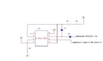
There is a positive feedback loop from 2OUT(pin7) to 2IN+ (pin5) via diode D1,
such that if the output 2OUT goes high, it stays high at 12V.
1OUT (pin1) s not shown connected. (x) but is a bipolar logic level sensing the state of 2OUT (pin7) by comparing 2IN+(pin5) to Gnd at 1IN+(pin3) .
If the 2IN-(pin6) from (filtered) PWM signal drops below 2IN+(pin5) (~5V? minus load IR drop) then the Overvoltage indicator goes hi on 2OUT(pin7) = 12V otherwise it is -12V.
Not sure , but thats what I see.
Hi all,
Can anyone help me to find out the IC details from the attached circuit diagram..
Is it comparator???
Reverse engineering is the process of discovering the technological principles of a device, object, or system through analysis of its structure, function, and operation. It often involves taking something (e.g., a mechanical device, electronic component, software program, or biological, chemical, or organic matter) apart and analyzing its workings in detail to be used in maintenance, or to try to make a new device or program that does the same thing without using or simply duplicating (without understanding) the original.
Jasonc2-
Some people recommend tying unused opamp inputs together to a voltage near ground. I have never liked that because the output of the opamp is always biased ready to swing from rail to rail for a small bit of noise pickup, or change in offset voltage, or any other wacko reason. The internal switching noise can theoretically disrupt the other opamp or at least add a bit of hard-to-find random noise to it. I prefer to put the inputs at least 1V apart just so the opamp will sit saturated with no chance of noise propagating through it.
Cool thanks for explaining it. I found a great article on it, written by James Bryant from Analog Devices:
https://www.analog.com/static/imported-files/rarely_asked_questions/unused_op-Amp_article.html
The recommended solution there is to configure it as a follower and tie the unused output to the inverting input and the noninverting input to some point in the circuit with voltage between the rails.
Careful if you sing the song to not let it get stuck in your head though. ... :-(
This MAXIM article gives the same advice: **broken link removed**
J
Good point Steve E. .I was assuming there were some other connections to drain current the reason for the 2 R's was to get twice shunt resolutionHow could opamp sink the 5V current if R2 R3 are current sense? Dead opamp most likely if you tried, unless the opamp is short-circuit rated.