yzriver
Member level 2
I am trying to generate a clock signal, and send data to control the device, with PIC18F2550.
The data starts early than the real clock signal (CLK), and there are two data (data1, data2) for each data stream circle. The time diagram of clk and data can be seen in the attachmentThe control device can accept up to 20MHz clock signal, but I am not that aggressive. I try to generate the clock at the range of 1MHz to 2MHz. The PIC18F2550 receives the data from PC through USB.
Can someone comment my method is good or not? Maybe you have better way.
In my way, I have a few problems. The first two are:
1. I can’t generat MHz clock from RB4, no matter how I set TMR0H and TMR0L.
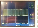
2. The period of the RB4 is changing. This code generate square wave to RB4, and won’t stop until I send 0xa1. Please see the waveform in the attachment.
This is the structure of the code with hi-tech C.
The PIC18F2550 keeps listening any command from USB
_______________________________________________
_______________________________________________________
If PIC18F2550 receives the 0xa1 from ReceivedDataBuffer[0], then start the interrupt of timer0. RB4 is the counting clock, RB3 is the CLK, and RB2 is the data. In Process IO(), I have
****************************************************
*********************************************************
The interrupt code:
+++++++++++++++++++++++++++++++++++++++++++++
********************************
The data starts early than the real clock signal (CLK), and there are two data (data1, data2) for each data stream circle. The time diagram of clk and data can be seen in the attachmentThe control device can accept up to 20MHz clock signal, but I am not that aggressive. I try to generate the clock at the range of 1MHz to 2MHz. The PIC18F2550 receives the data from PC through USB.
Can someone comment my method is good or not? Maybe you have better way.
In my way, I have a few problems. The first two are:
1. I can’t generat MHz clock from RB4, no matter how I set TMR0H and TMR0L.
2. The period of the RB4 is changing. This code generate square wave to RB4, and won’t stop until I send 0xa1. Please see the waveform in the attachment.
This is the structure of the code with hi-tech C.
The PIC18F2550 keeps listening any command from USB
_______________________________________________
Code:
void main(void)
{    InitialiseSystem();
    while(1)    {        USBDeviceTasks();
        ProcessIO();
    }
}If PIC18F2550 receives the 0xa1 from ReceivedDataBuffer[0], then start the interrupt of timer0. RB4 is the counting clock, RB3 is the CLK, and RB2 is the data. In Process IO(), I have
****************************************************
Code:
if(!HIDRxHandleBusy(USBOutHandle))
    {
        switch(ReceivedDataBuffer[0])
case 0xa1:
                            T0CON = 0b11001000;   // enable TIMER0, 1/8 F
                            TMR0H = 0x00;
                            TMR0L = 0x01;
                            if  (TM0_INT==0) {
                                       TMR0IE=1;                       //open TMER0 interrupt
                                       TM0_INT=1;
                            }
                            else{
                                    TMR0IE=0;                       //close TMER0 interrupt
                                    TM0_INT=0;
                                    RB4=RB3=RB2=0;
                                    t=0;
                            }
break;The interrupt code:
+++++++++++++++++++++++++++++++++++++++++++++
Code:
void interrupt tmr0_int(void){
  TMR0IE=0;                              // close TMER0 interrupt
  TMR0IF=0;                              // claer TMER0 interrupt flag
  t++;
  if (t==1){
             RB4=0;
             RB3=1;
             RB2=1;
  }
  else if (t==2){
             RB4=1;
             RB3=1;
             RB2=1;
  }
  else if (t==3){
             RB4=0;
             RB3=1;
             RB2=1;
  }
  else if (t==4){
             RB4=1;
             RB3=1;
             RB2=1;
  }
:
:
:
else if (t==91){
             RB4=0;
             RB3=0;
             RB2=0;
  }
  else if (t==92){
             RB4=1;
             RB3=0;
             RB2=0;
  }
  else if (t==93){
             RB4=0;
             RB3=0;
             RB2=0;
  }
  else if (t==94){
             RB4=1;
             RB3=0;
             RB2=0;
  }
  else if (t==95){
             RB4=0;
             RB3=0;
             RB2=0;
  }
  else if (t==96){
             RB4=1;
             RB3=0;
             RB2=0;
             t=0;
  }
  TMR0IE=1;                            // open TMER0 interrupt
}Attachments

Last edited by a moderator: