Vermes
Advanced Member level 4
This is a description of home made SymAsym amplifier with Revox preamplifier. All resistors, transistors and capacitors should be selected and paired to gain the best possible quality of operation of the power amplifier. Quiescent current was set at 100mA.
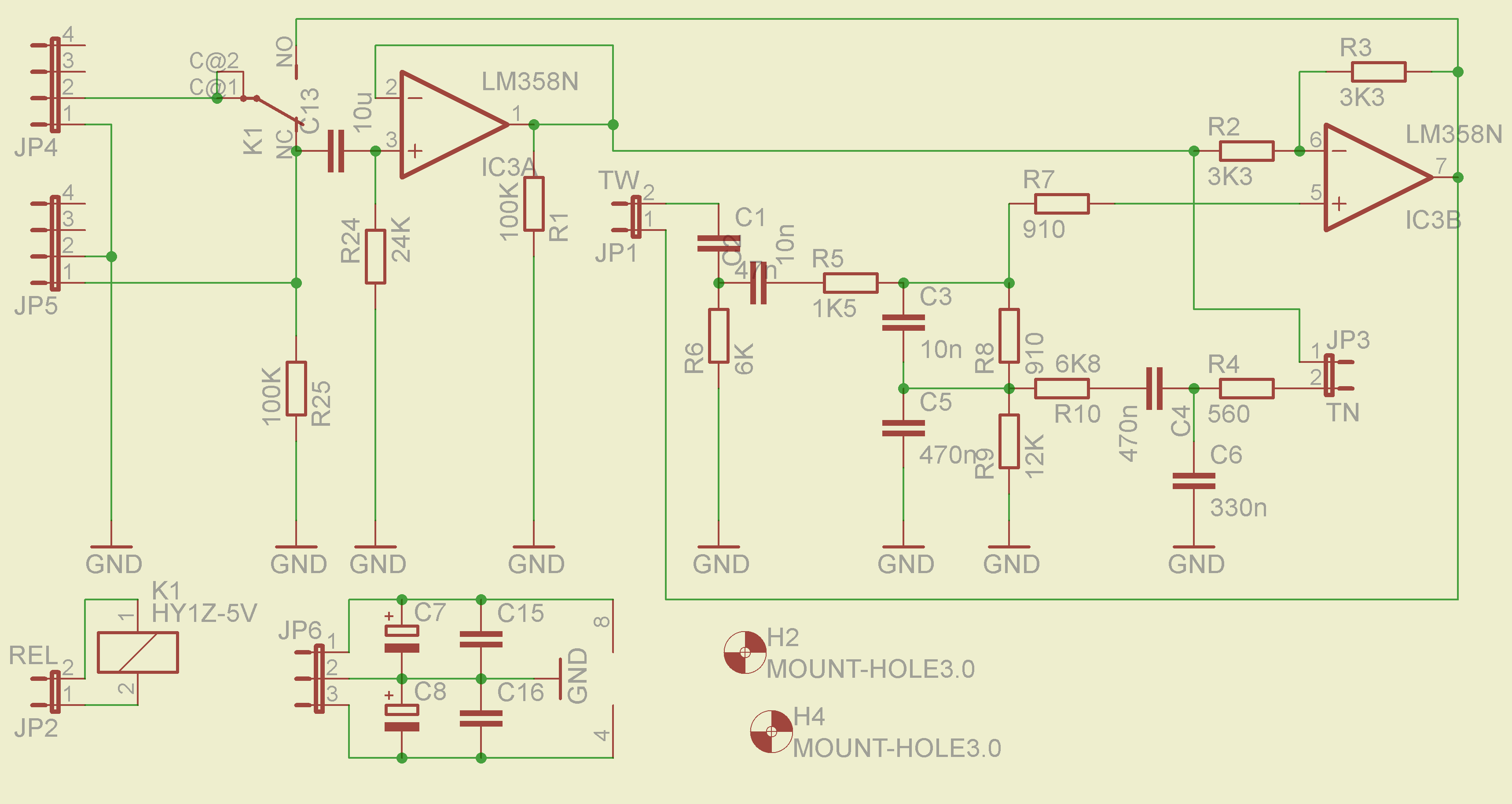
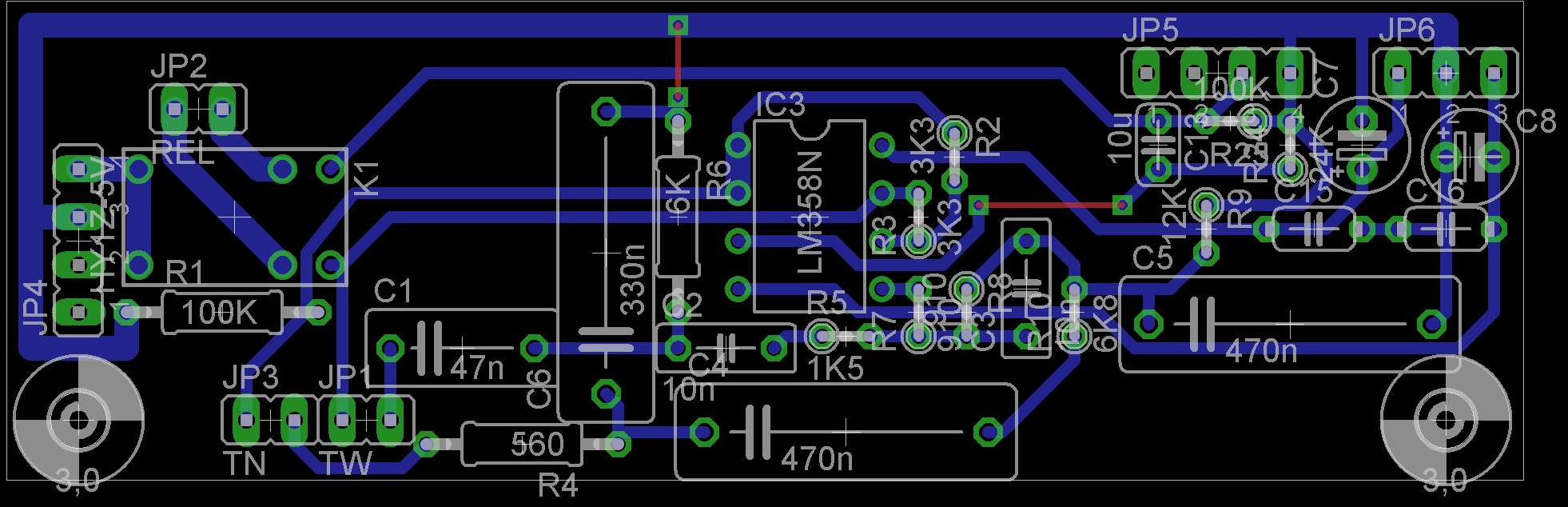
Preamplifier was implemented according to the schematic from: LINK. In addition there are repeaters on operational amplifiers before the corrector. Two double operationa amplifiers NE5532 were used per a channel. Circuits were applied in stands, so you can easily test other operational amplifiers. PCBs can be home made and adapted to your electronic components. PCBs of both channels differ from each other because of their terminals. They are mounted one above another, connected by HEADERS. Signal and supply cables are derived from one PCB. Corrector is supplied by +-18V.
Pictures showing one PCB:
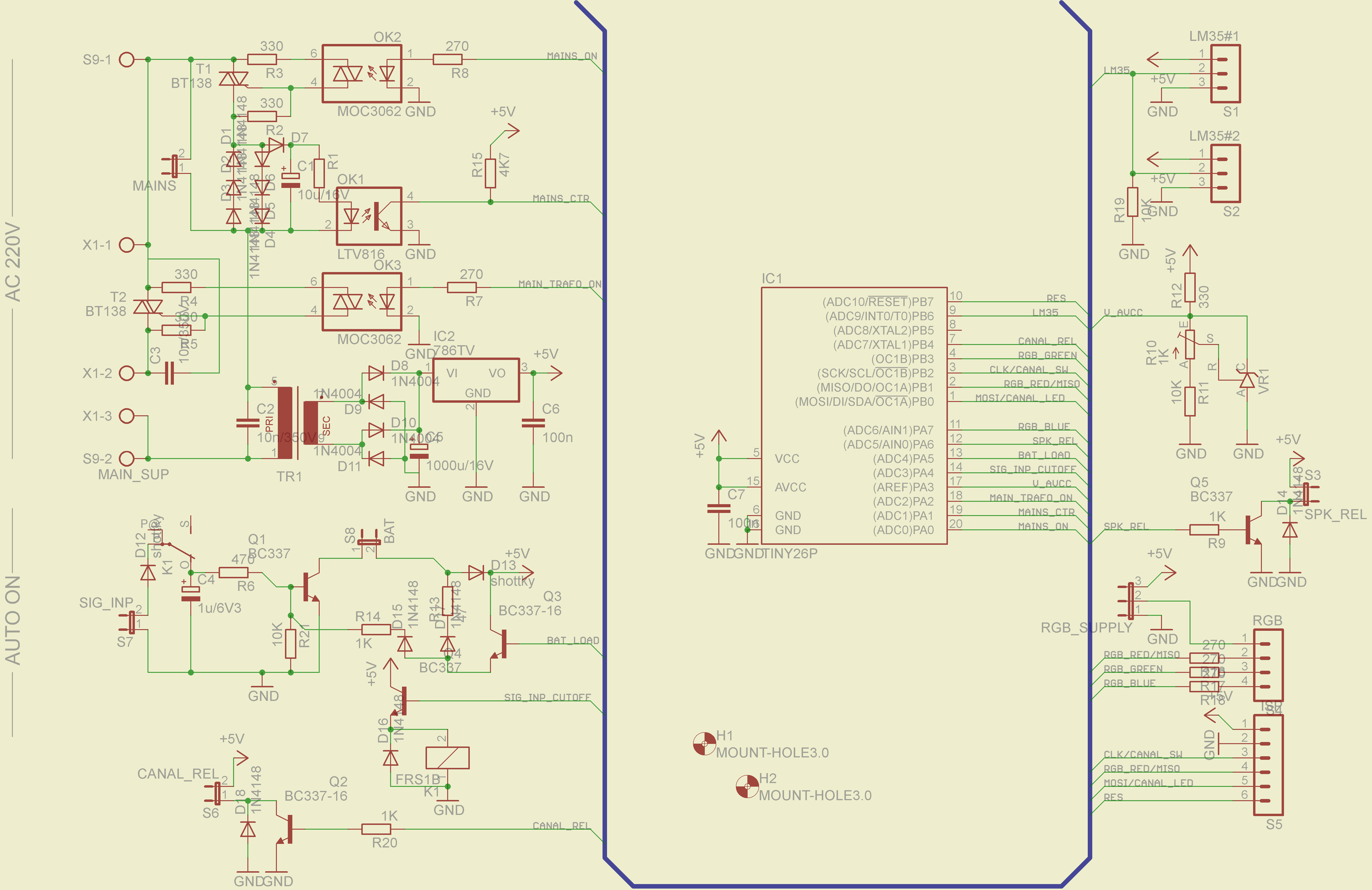
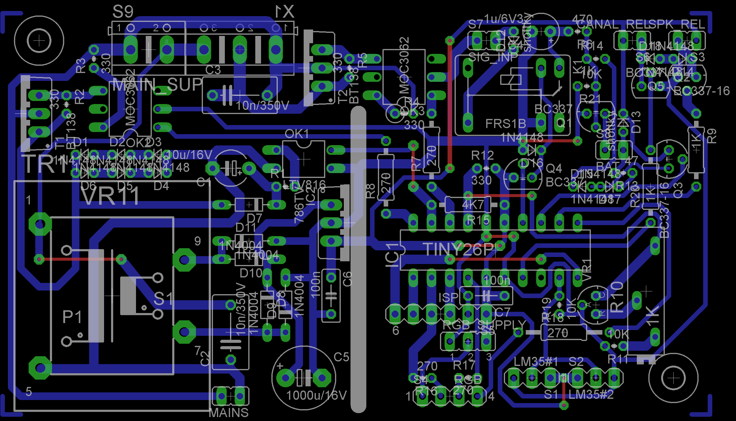
Control system turns on and off the amplifier by a button, turns on and off two-point corrector (and remembers if previously it was on or off), controls all the relays in the amplifiers and backlight of the knobs.
Additional functions of switching system:
- automatically turn on the amplifier with inside audio signal
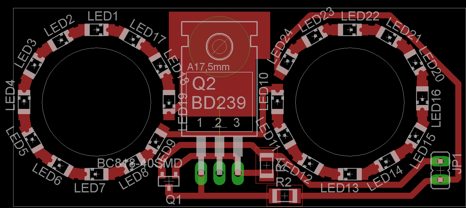
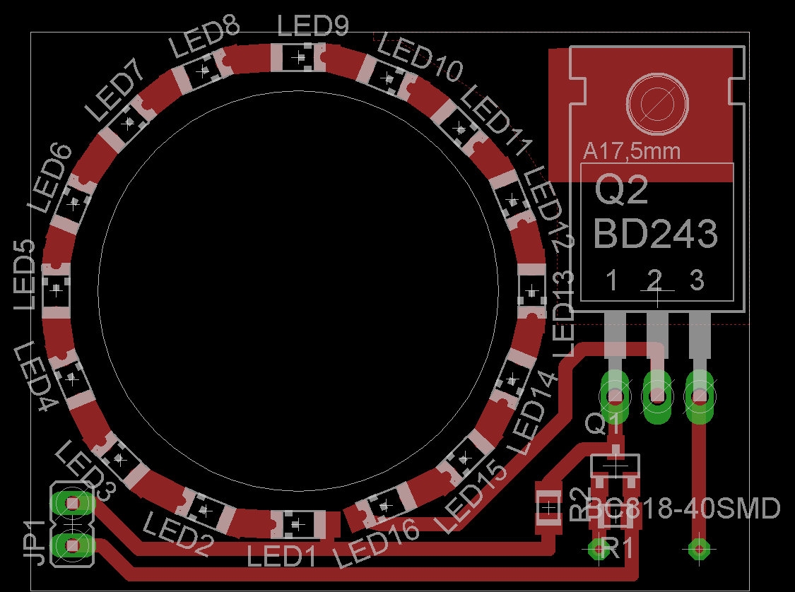
- measure temperature and adequately to it color the rims behind knobs with RGB LEDs, and after exceeding a given temperature of heat sinks, turn off the speakers
Thus the system based on Attiny26 is quite large and the program was written in C.
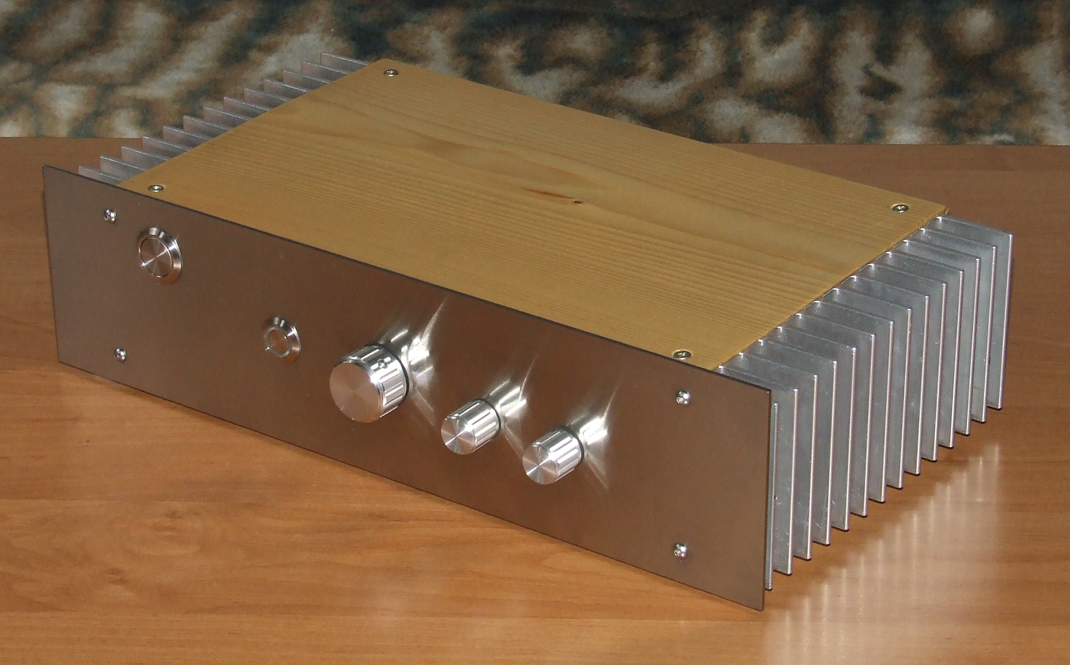
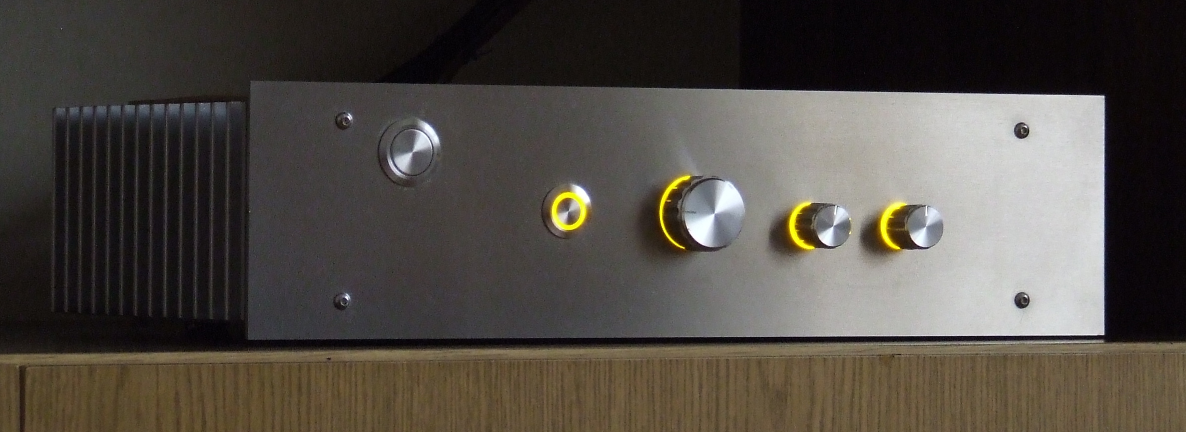
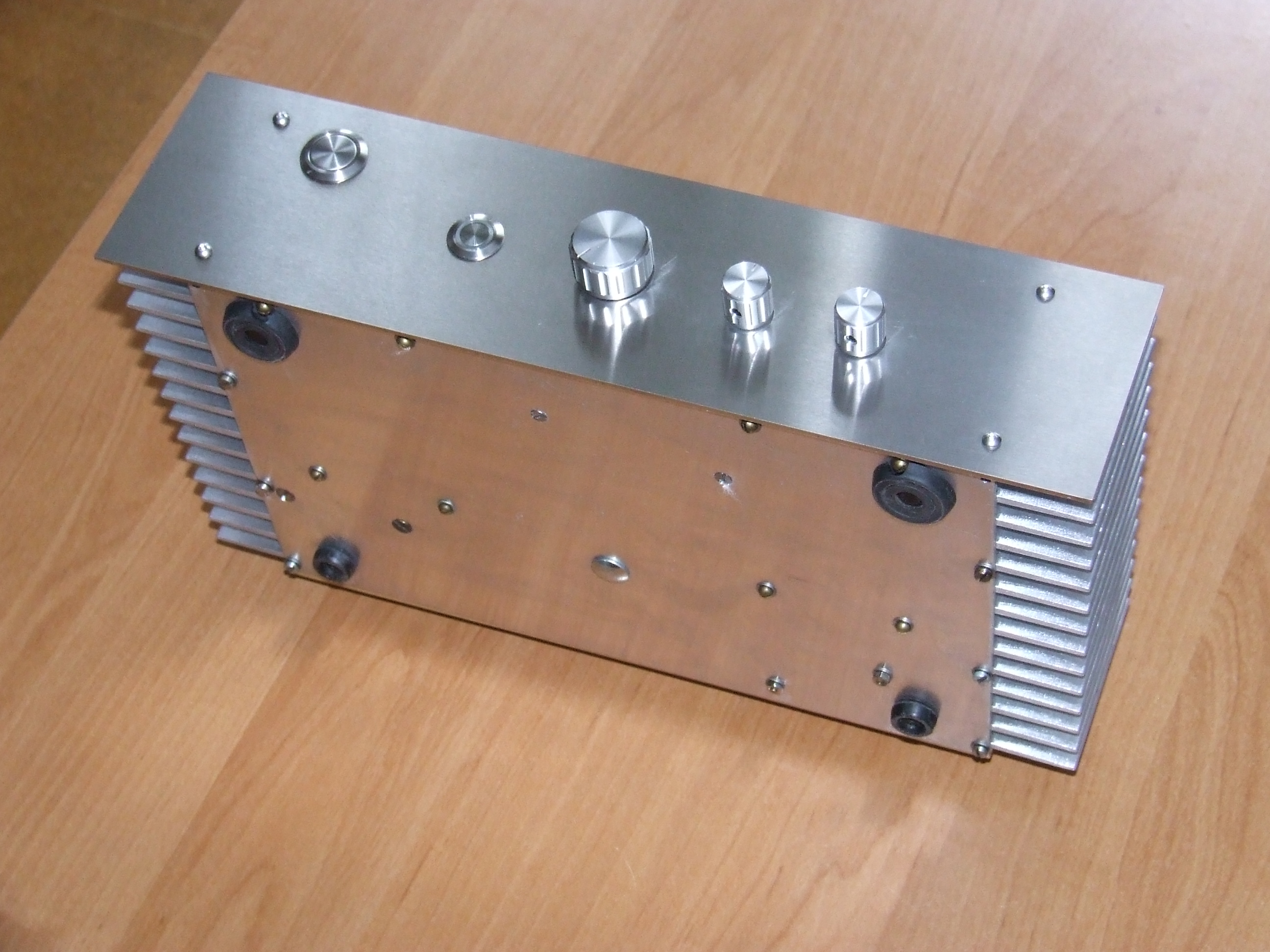
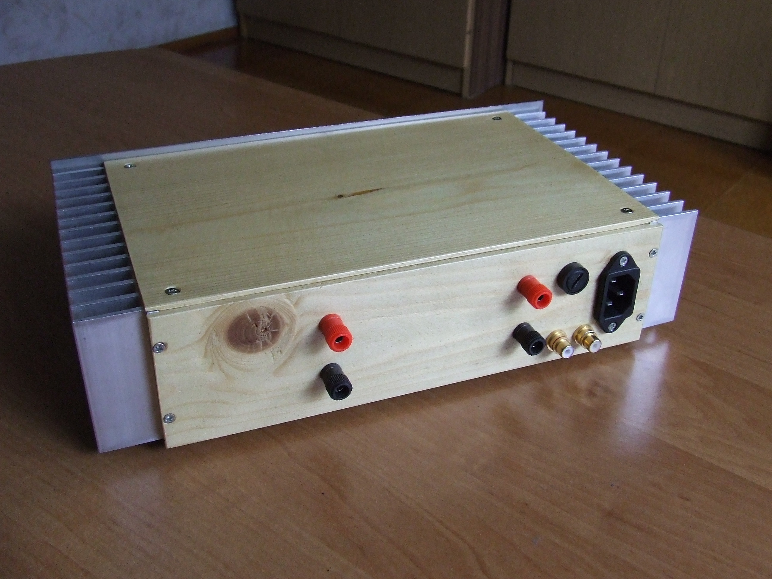
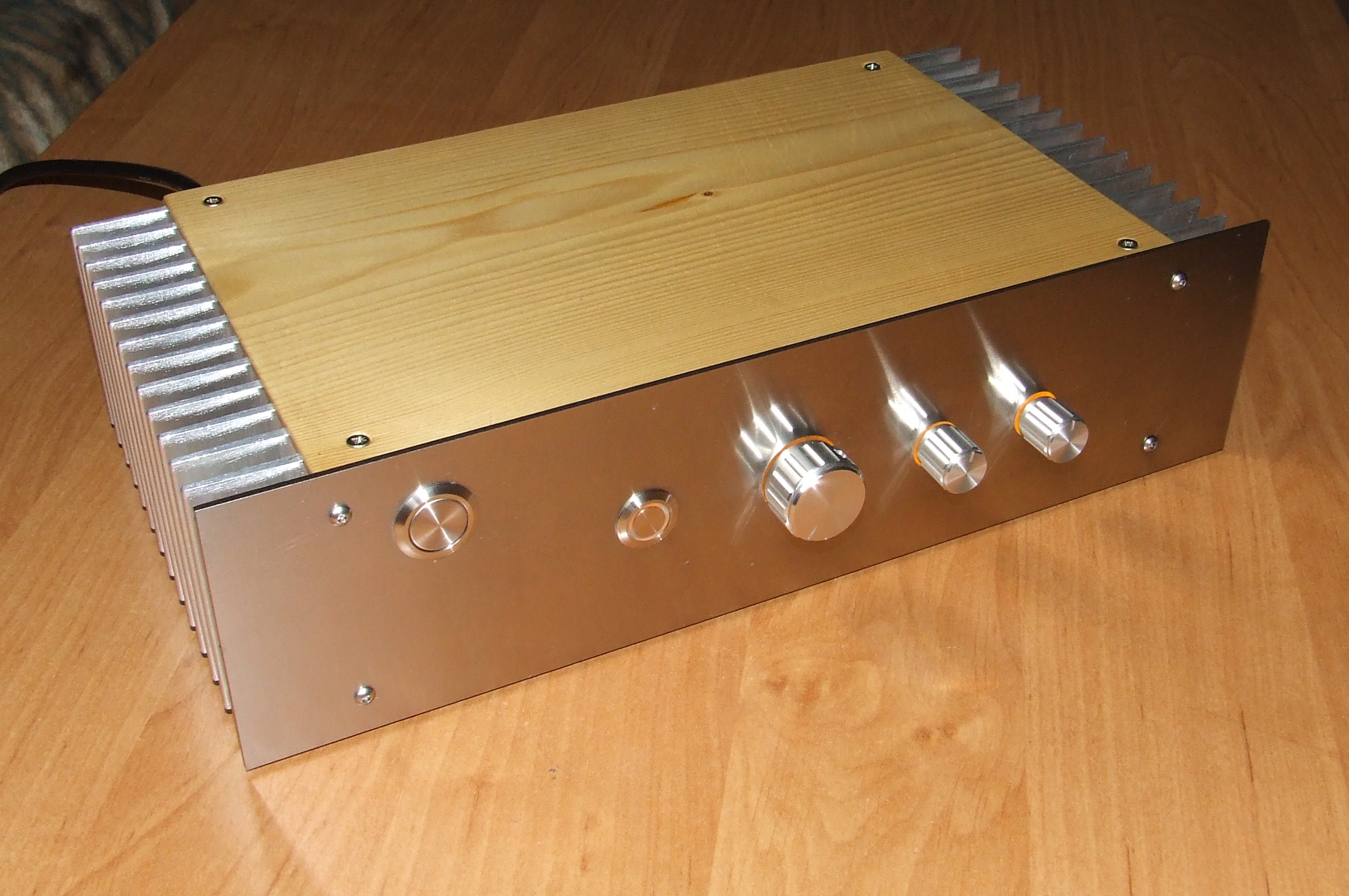
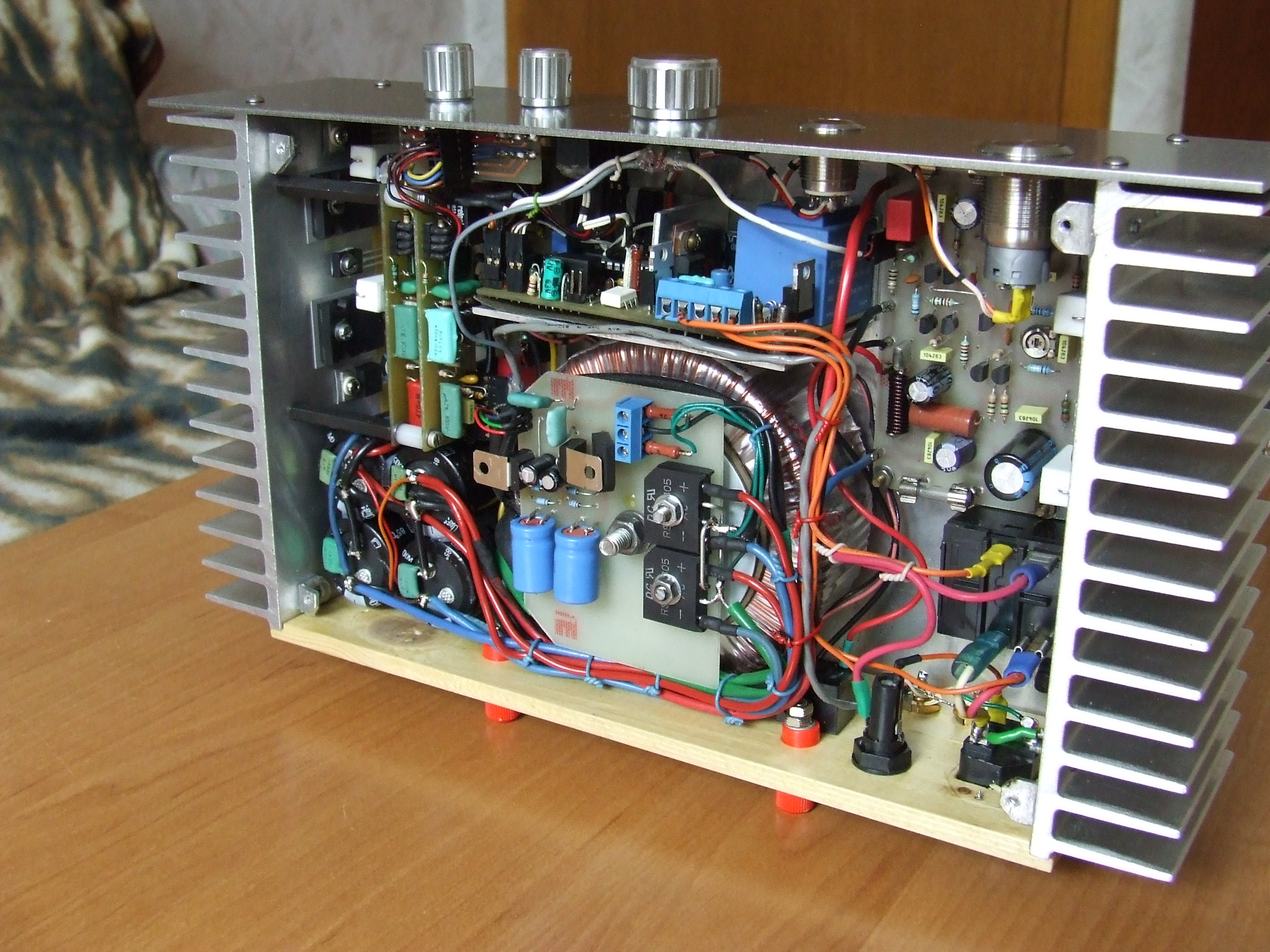
Remember that the housing must be adapted to heat sinks. It should provide right cooling to power transistors. It is good to measure the given power in the form of heat using a lab power supply and transistor. Then cut a piecec of metal sheet and mount the components. In this design, the housing was decorated with elements of varnished wood. Front panel was made of polished metal chrome nickel. The distribution of potentiometers is typical: volume, bass and treble regulation.
All the PCBs have connectors based on HEADERs (except the PCB of switching system with high mains voltage and power amplifiers supply). Thus, assembly and disassembly does not require soldering. Grounds of both channels are not common, but shorted at the input and connected with the ground adn housing.
Backlight was based on SMD LEDs connected in series to the current sources. Systems were connected to the power supplies of both channels and they can be switched by relays.

The amplifier consumes in total 110W at 8ohm load. Separately both channels have a power of 64W. Noises of the power amplifiers at volume potentiometer turned to the left are approximately 2mV. Frequency response for the decrease in the amplitude of -3dB is from about 1Hz to 440kHz.
Link to original thread - Symasym z korektorem Revox