Continue to Site

Welcome to EDAboard.com

Welcome to our site! EDAboard.com is an international Electronics Discussion Forum focused on EDA software, circuits, schematics, books, theory, papers, asic, pld, 8051, DSP, Network, RF, Analog Design, PCB, Service Manuals... and a whole lot more! To participate you need to register. Registration is free. Click here to register now.

Even-Odd-Analysis Coupling Structure

Status
Not open for further replies.

frischling

Newbie level 2
Joined
Jul 13, 2012
Messages
2
Helped
0
Reputation
0
Reaction score
0
Trophy points
1,281
Activity points
1,296
Hello everyone,
I might need your help!!

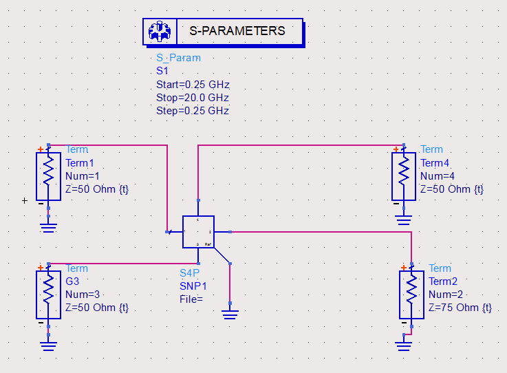
I have a touchstone file (s4p, S-Paramter) describing a coupling structure including two 'transmission lines'. Now I want to make an eve-odd-analysis using a circuit simulator (ADS). Do you know how to find out the even/odd impedance and the characteristic impedance matrix for the entire structure? The characteristic impedance of one such file is about 58Ohm and almost over the frequency. The system impedance is 50Ohm. How should I terminate the ports to find out the impedances?

Thank you for your help


I think you should write equations in Data Display Window.
See "RF and Microwave Coupled-Line Circuits"Rajesh Mongia,Inder Bahl,Prakash Bahrtia.Artech House 1999 (Page124-130)
 
Last edited:

Use two ADS ports (Term) instead of four. Connect them to get the desired mode.

For differental mode, connect each of them between a pair of ports in the S4P block, so that the "-" terminal of the port is connected to a S4P port and not to ground.

For common mode, connect the pairs of ports in the S4P block in parallel. In this case, the "-" terminal of the ADS port (Term) is grounded.

Note that this measures and terminates one mode, without properly terminating the other model. To measure both modes at the same time, you could use an ideal center tapped transformer to separate the modes. In AWR Microwave Office, there's a nice "MMCONV" element for that purpose.
 

Thanks all!

@Volker

I've tried out your suggestions. I set the port impedance in order to minimize S11 and maximize S12. With that values I can now calculate the characteristic impedance matrix ele ments with the equations:

\[{Z }_{diff } = 2({Z}_{0,11}-{Z}_{0,12})\]

\[{Z }_{comm} = 1/2({Z}_{0,11}+{Z}_{0,12})\]


Finally, I have the complete characteristic impedance matrix (symmetric structure):

\[{Z }_{0} = [{Z}_{0,11}\, {Z}_{0,12}\\
\quad \quad \quad \quad \quad \quad \quad {Z}_{0,12}\, {Z}_{0,11}]\]

Is that right?
 

Sorry, I don't know. I am not familiar with this Z0 matrix that you are looking for.

Z0e = 2 * Zcommon
Z0o = 1/2 * Zdifferential

but this is for pure common/differential mode and does not include mode conversion.
 

Status
Not open for further replies.

Part and Inventory Search

Welcome to EDABoard.com

Sponsor

Back
Top