Continue to Site

Welcome to EDAboard.com

Welcome to our site! EDAboard.com is an international Electronics Discussion Forum focused on EDA software, circuits, schematics, books, theory, papers, asic, pld, 8051, DSP, Network, RF, Analog Design, PCB, Service Manuals... and a whole lot more! To participate you need to register. Registration is free. Click here to register now.

Current Limiter Circuit Design

Status
Not open for further replies.

jasonc2

Full Member level 4
Joined
Jun 23, 2012
Messages
204
Helped
25
Reputation
52
Reaction score
25
Trophy points
1,328
Location
NYC, USA
Activity points
3,415
I am experimenting with current limiting methods in a simulator. I have this:


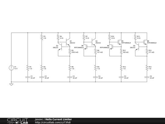
C1 just charges with 12A.

C2 is limited to 3A @ 12V with a resistor.

C3 is limited to 3A @ 12V with a limiting circuit from **broken link removed**.

This is the current for C3 as it is charging:

1tu7q0.jpg


My question is, is there a way to flatten the curve a little more around 3A and have a sharper drop off when the current goes below 3A? I've been trying different designs, tweaking things, but I can't get my head around it. Right now it drops down to about 2.5A at T=60ms, but I'd like to minimize that drop. Are there other designs with a flatter limiting curve?

Thanks!
J

- - - Updated - - -

I've gotten a little closer by using a MOSFET for Q2 (I guess my circuit diagram above updates when I save changes on CircuitLab). I'll post the graph when the simulation is done, which hopefully will happen some time this week... :-|
 

Maybe you could try a constant-current source set for 3A. It would be flat up until the point where the voltage on the cap gets close to the rail
 
  • Like
Reactions: jasonc2

    jasonc2

    Points: 2
    Helpful Answer Positive Rating
You have a series capacitor in all the limiter outputs, which means the circuits don't carry DC. Are you trying to make some type of capacitor charging limiter? :?:
 

Thanks! Here is the result of experimenting with MOSFETS.

2ds3951.png


C5, using MOSFETS for both transistors, is the closest I've gotten to my goal so far.

Maybe you could try a constant-current source set for 3A. It would be flat up until the point where the voltage on the cap gets close to the rail

Good idea I'll do some research and see what I can come up with.

You have a series capacitor in all the limiter outputs, which means the circuits don't carry DC. Are you trying to make some type of capacitor charging limiter? :?:

Yes it is a capacitor charge limiter. I'm playing with current limiting in general, and I picked charging capacitors because it seemed like good test case. But, it was initially inspired by a high current bench power supply I was trying to design (and failed -- I'll probably be asking about it in here at some point, but I want to try and get as far as possible on my own first).

J
 
Last edited:

The type of current limiting you're using is a basically a pretty crude control loop. You could get fancy and put an amplifier and compensation network, etc., and get sharper control, but to what end? What are you REALLY trying to accomplish? Do you want to maintain a constant current? A constant voltage?
 

I tried using a Howland current source derived from https://www.circuit-fantasia.com/ci...and_current_source/howland_current_source.htm. It works great with an "ideal" op-amp with no output resistance, but any > 0 output resistance on the op-amp causes the circuit to behave much more like the simple resistor limiter:


C2 is just a resistor.
C5 is the best results I got with MOSFETs above.
C7 uses a constant current source with a 0-ohm op-amp - this is the type of curve I'm trying to get.
C8 uses an op-amp with 50 ohm output impedance.

2qm3gxd.png


I will continue researching other types of constant current sources.

What are you REALLY trying to accomplish? Do you want to maintain a constant current? A constant voltage?

I want to clip to a maximum current, with ideally no effect on current flow below the maximum (e.g. like the C7 curve in the above graph).
 
Last edited:

The load lines are limited by the ratio of (Rbase * gain )/ R emitter ratio.. with R emitter defining the 1st slope.. Using a smaller resistor will flatten the curve and using a comparator to reduce the offset fro say 0.6V to 0 makes it sharper. so it is 3A till fully charged then cuts off. But I am not sure you want that much ripple current in the cap. but thats another question. To make a flat CC source you need a precision ref and comparator or high gain loop. One such solution is the LM317 3 terminal regulator with 1.25V Vref and putting I max = 1.25V/Rs The down side is the drop is so high it limits the practical application from large power dissipation.. So a better solution would use say 100mΩ MOSFETS with voltage gain on a 100mΩ shunt resistor and high gain on regulating the MOSFET Gate. Get the picture... Then use PTC MOSFETS in parallel for scalability like the Tesla Car. I think it uses 850 MOSFETs.

- - -
The limitation of all high current sources is how much gain can you get to regulate a CC source @ 100% efficiency. i.e. a 2 terminal device that does not waste driver current to ground of V+ and thus all regulated current goes into the load? This turns out to be harder than it looks without have a large saturation voltage. even using an LDO 3 terminal regulator as a CC 2 pin source.

The 2 terminal CC IC's may be a clue in how to configure a high gain differential pair to drive NPN to PNP with very high gain at low saturation voltage and high current... Also not easy as these are tradeoffs.

Screen shot 2012-07-12 at 7.18.24 PM.png I believe a discrete version of this using MOSFETs may be a better solution for a maximal flat CC source with minimum drop voltage. Consider ROHM for high gain bipolar Q's or others for Mosfets.
 
Last edited:
  • Like
Reactions: jasonc2

    jasonc2

    Points: 2
    Helpful Answer Positive Rating
Thanks for all your help guys. I found awesome guide to op amps at https://www.allaboutcircuits.com/vol_3/chpt_8/1.html, so I've been finding all sorts of neat solutions.

@SunnySkyguy: Wow thanks, lots of good advice. What is the double ring symbol labelled 10uA in that little diagram you posted?
 

Status
Not open for further replies.

Similar threads

Part and Inventory Search

Welcome to EDABoard.com

Sponsor

Back
Top