Continue to Site

Welcome to EDAboard.com

Welcome to our site! EDAboard.com is an international Electronics Discussion Forum focused on EDA software, circuits, schematics, books, theory, papers, asic, pld, 8051, DSP, Network, RF, Analog Design, PCB, Service Manuals... and a whole lot more! To participate you need to register. Registration is free. Click here to register now.

Microcontroller resets when activating relay for Solenoid Valve

Status
Not open for further replies.

lloydi12345

Member level 4
Joined
Aug 31, 2010
Messages
77
Helped
5
Reputation
10
Reaction score
5
Trophy points
1,288
Activity points
1,953
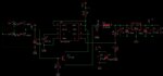
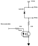
Resetting happens whenever the microcontroller activates the relay that turns on the solenoid valve for controlling the pressure passage. Microcontroller controls the relay through 4n30 opto isolator. The whole circuit shares the same power supply which is approx 31VDC (from 24VAC). 31VDC is stepped down to 9V through switching regulator and regulated again through 7805 which powers the microcontroller. The rating of the relay is 28VDC. Also, 31VDC is connected to one side of relay and the other side is connected to a resistor then to the collector of 4n30. I placed 1N4148 diode across the relay pins which serves as the protection.

4n30 connections:
pin 1 - connected to 330 ohms to microcontroller pin
pin 2 - connected to gnd
pin 4 - connected to gnd
pin 5 - connected to 330 ohms to the other side of relay.
pin 3 and 6 are hanging

Can you help me with this one? thanks.

Regards,

lloyd

- - - Updated - - -

I would like to add something. When the microcontroller controls only the relay, the circuit works fine but when the solenoid is connected the problem then arises.
 

Attachments

  • schemeit-project.png
    schemeit-project.png
    11 KB · Views: 302
Last edited:

your problem is the noise. The switching triggers a noise which resets the controller. How does the isolator serve its purpose if both i/p and o/p are having the same Ground?
you could first switch a smaller relay (SPST) which in turns drive this solenoid relay.
 
What are the current or power ratings of the said power supply?

Can you provide a schematic of the power supply section?

The symptoms you describe are often be attributed to exceeding the power supplies maximum ratings for current or the presences of Back EMF.

Have you utilized bypass capacitors on Vdd and Vss of microcontroller?

Can you elaborate on the specifics of the relay used in your design or post a link to it's datasheet?

What is the exact microcontroller used in the design?


BigDog
 
your problem is the noise. The switching triggers a noise which resets the controller. How does the isolator serve its purpose if both i/p and o/p are having the same Ground?
you could first switch a smaller relay (SPST) which in turns drive this solenoid relay.

Hi cameo_2007, please suggest any diagram?

What are the current or power ratings of the said power supply?
The transformer that feeds my power supply rectifier is rated with 24VAC 1.5A
Can you provide a schematic of the power supply section?
Please check my attachment
Have you utilized bypass capacitors on Vdd and Vss of microcontroller?
Yes these are present.
Can you elaborate on the specifics of the relay used in your design or post a link to it's datasheet?
I am using MY4N it's from OMRON
What is the exact microcontroller used in the design?
I'm using PIC18F4620

Thank you for your help guys :)

- - - Updated - - -

Edit: I am required to use only one power source which is 24VAC so I can't use another one for controlling the relay. I've read from other posts that adding capacitor on MCLR pin solves the problem. I haven't tried it yet though.
 

Attachments

  • power supp.jpg
    power supp.jpg
    69.8 KB · Views: 213

Hi,

You do not mention what voltage the Solenoid is running at.

Have you added a contact suppessor either across the relay contacts or across the solenoid ?

Also if you have any input connections to the pic that are not shielded they will readily pick up interference.
 
Hi, I think the solenoid is functioning at 220VAC. What do you mean with contact supressor? Is it the diode accross? Yes I have them.

I'm reading an analog voltage on the RA0 of the PIC.

Is it possible to create two grounds in just one power source? I'm thinking about the ground of the microcontroller then another ground for opto isolator. What do you think? Anymore ideas?
 

I'm using PIC18F4620


Edit: I am required to use only one power source which is 24VAC so I can't use another one for controlling the relay. I've read from other posts that adding capacitor on MCLR pin solves the problem. I haven't tried it yet though.

Disable MCLR in the configuration fuses. Also disable Brownout Detect.
 
Thanks ard for the suggestion! I'll place that on my to do list. :)

More ideas please....


Any hints what values of capacitor and resistor that I could use for CR Type?
faq02804_01.jpg
 

Any hints what values of capacitor and resistor that I could use for CR Type?
]

Hi,

Am no expert on suppression, its a complex area.

You are probably better buying a ready made RC block like this, rather than separate components.
Most electrical shops should stock something similar and lo cost.

The important thing is that they are properly rated at main voltage for your area .. 230v ?? So capable of 250vac
Ordinary caps are no good they need to be whats known as class X or Y.

https://www.farnell.com/datasheets/7032.pdf
 

The suppression circuit to which you are both referring, is commonly referred to as a Snubber, which is essential an RC or RCD circuit.

As wp100 commented the topic can be complex as the calculations are dependent on several factors.

The topic has been discussed numerous times, throughout the forum, search for keyword "snubber."


The following are a few external references to get you started in the right direction:

DESIGN OF SNUBBERS FOR POWER CIRCUITS

Snubber Circuit Design - Practical Tips

Snubber Circuit Design Calculators

**broken link removed**


BigDog
 

Could you please tell us how could you solve your problem?

I am working on a new design which will run 16 solenoids at a time by a PIC. I am not sure what will be the problems that will occur =).

Solenoid specs are 24v DC solenoid with 700 ohm resistance. there is my shematic.

Should i use 1n4007 diode or varistor?

Should i need a zener diode in paralel to mosfet?

And ,ofcourse, should i add a snubber circuit to this desing.

We will run this solenoids only for 20ms at a time and 2 times in a second maximum.

Untitled.png
 

Status
Not open for further replies.

Part and Inventory Search

Welcome to EDABoard.com

Sponsor

Back
Top