Continue to Site

Welcome to EDAboard.com

Welcome to our site! EDAboard.com is an international Electronics Discussion Forum focused on EDA software, circuits, schematics, books, theory, papers, asic, pld, 8051, DSP, Network, RF, Analog Design, PCB, Service Manuals... and a whole lot more! To participate you need to register. Registration is free. Click here to register now.

How to compensate the phase error introduced by a low pass filter?

Status
Not open for further replies.

powersys

Advanced Member level 1
Joined
Nov 29, 2005
Messages
439
Helped
3
Reputation
6
Reaction score
2
Trophy points
1,298
Activity points
4,981
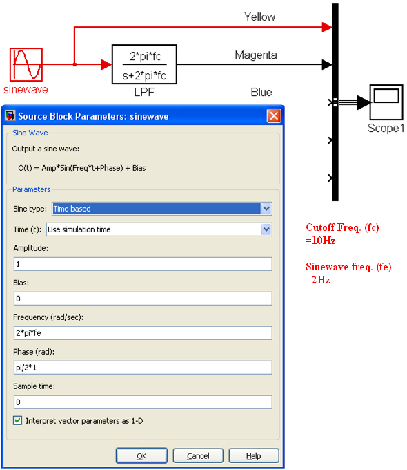
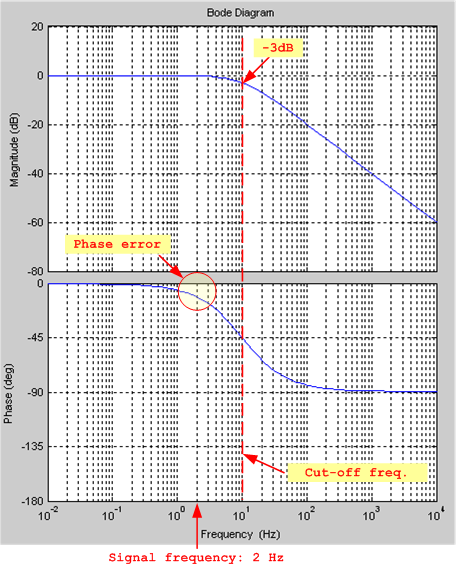
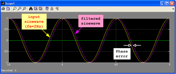
The first figure below shows the MATLAB/Simulink model of a low-pass filter (LPF). The cut-off frequency of the LPF is fc=10Hz. The sinewave frequency is fe=2Hz. As shown in the 2nd figure below, the LPF introduces a phase error at fe=2Hz, resulting in a filtered sinewave with phase error (see 3rd figure below).

Is there a method to compensate the phase error (which is applicable in Simulink or a microcontroller based application)?

Thanks.

93_1341319008.png


65_1341319125.png


44_1341319008.png
 

You can follow your LPF with an all-pass filter (or some other phase-compensating network) to adjust the phase.
 

You can add more phase shift with an all-pass filter, but you can't remove the phase shift added by the low-pass filter.
 

You can add more phase shift with an all-pass filter, but you can't remove the phase shift added by the low-pass filter.

Of course. If your requirement is to have the input->output phase=0 (or. really, 360) then you can do it. Otherwise you need a time machine.
 

Powersys,

are you really sure that your application requires to compensate this phase "error" ?
By the wy, I wouldn´t call it "error" because it is a natural physical phenomenon, see Bode`s fundamental formula for the gain-phase relationship.
 

Status
Not open for further replies.

Similar threads

Part and Inventory Search

Welcome to EDABoard.com

Sponsor

Back
Top