Continue to Site

Welcome to EDAboard.com

Welcome to our site! EDAboard.com is an international Electronics Discussion Forum focused on EDA software, circuits, schematics, books, theory, papers, asic, pld, 8051, DSP, Network, RF, Analog Design, PCB, Service Manuals... and a whole lot more! To participate you need to register. Registration is free. Click here to register now.

pwm using AT89C51 MICROCONTROLLER

Status
Not open for further replies.

raghurocks

Member level 1
Joined
Jul 3, 2012
Messages
33
Helped
2
Reputation
4
Reaction score
0
Trophy points
1,286
Location
India,Gujarat
Activity points
1,568
hello everyone,
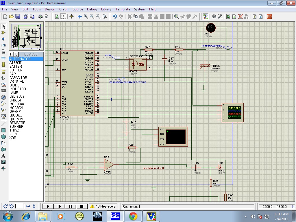
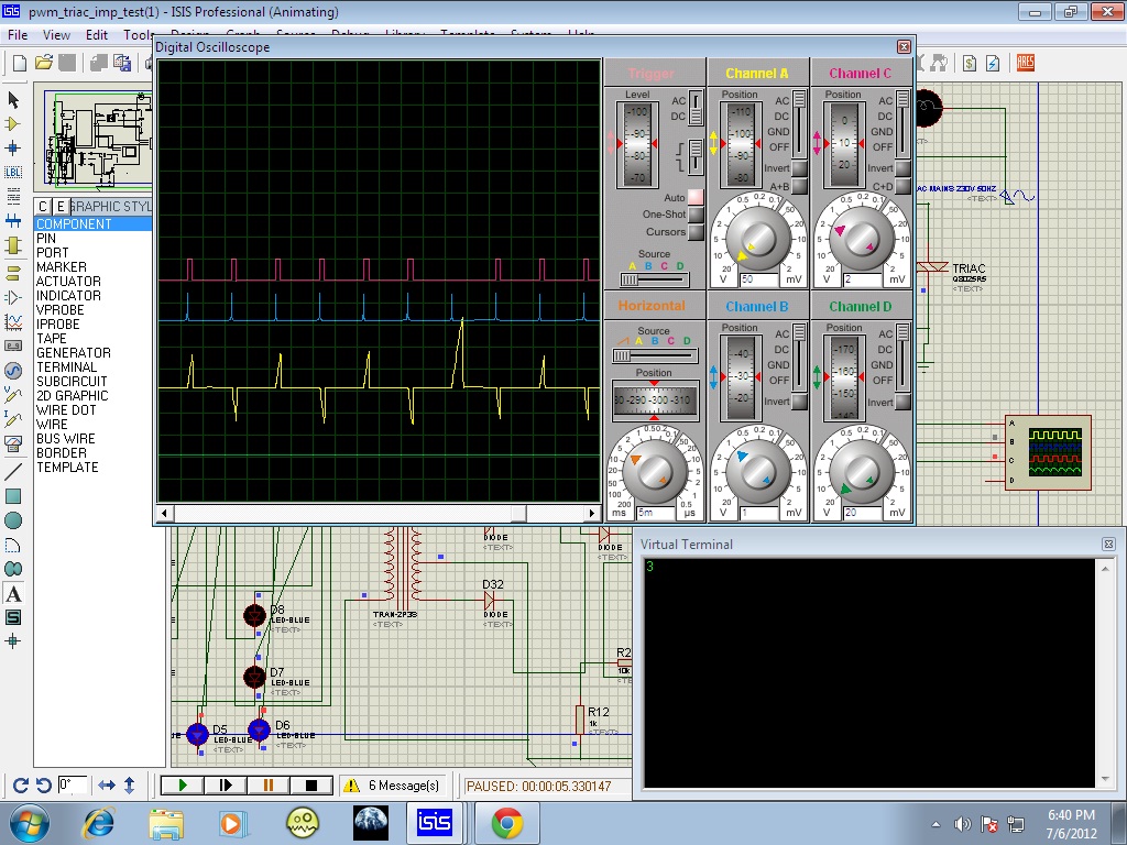
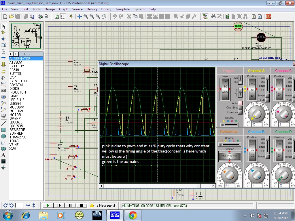
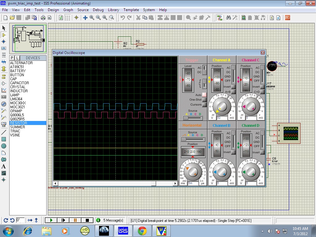
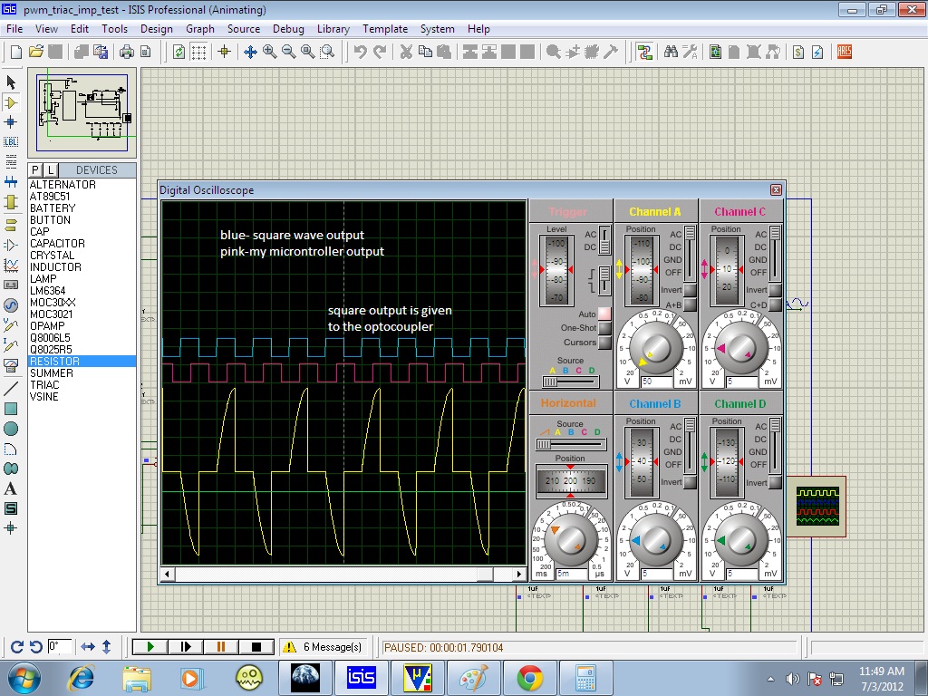
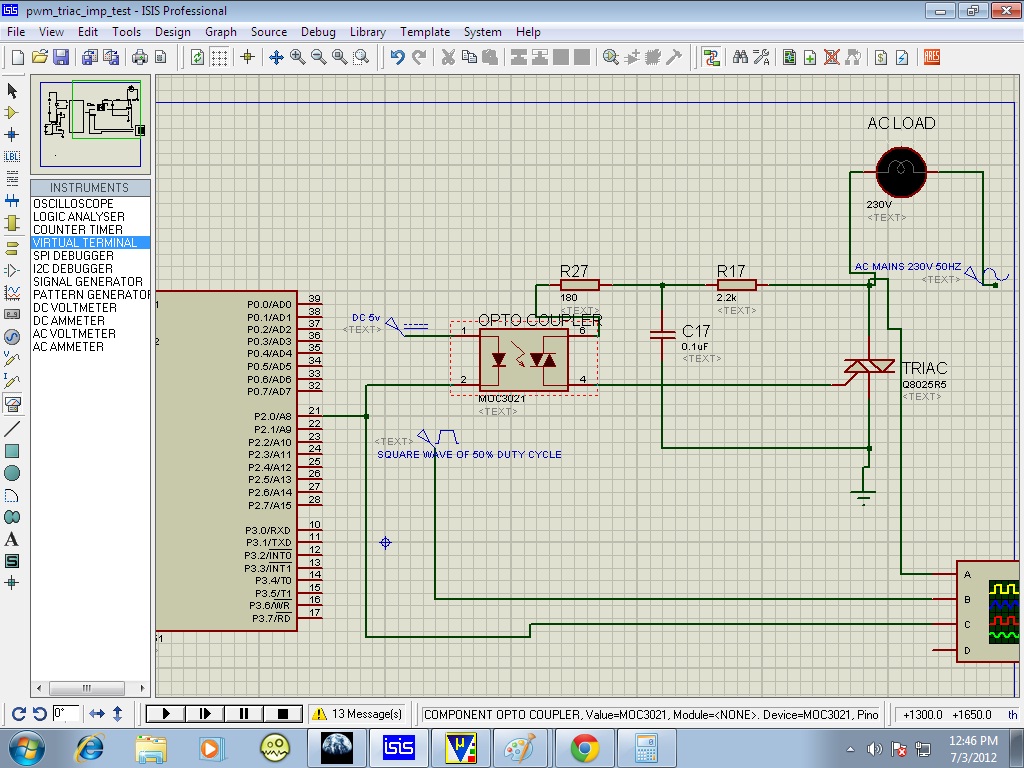
I have generated a pwm signal with 50% duty cycle using the timer concept but i don't know why I am getting a 60 degrees phase shift in the output wave so that if I compare with a standard square wave from a square wave generator my wave is keep on shifting may I know the reason......
Thanks in advance


Here is my code used for that generation(a pulse of 100hz and 50%duty cycle)


Code ASM - [expand]
1
2
3
4
5
6
7
8
9
10
11
12
13
14
15
16
17
18
19
20
21
22
23
ORG 00h
MOV SCON,#05H
MOV TMOD,#10h
MAIN:
SETB P2.0
MOV TL1,#00h//5 MSEC
MOV TH1,#0EEH
CALL DELAY
 
CLR P2.0
MOV TL1,#00H
MOV TH1,#0EEH
CALL DELAY
 
SJMP MAIN
 
DELAY:
SETB TR1
L1:JNB TF1,L1
CLR TF1
RET
 
END

 
Last edited by a moderator:
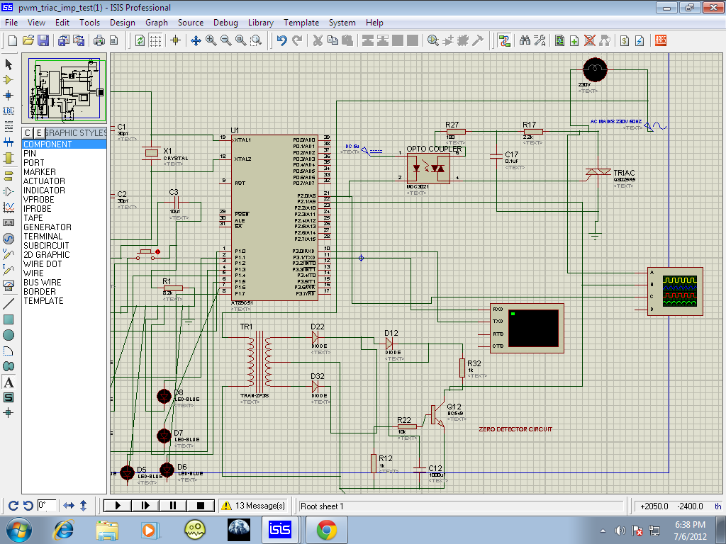
Why would the square wave from the function generator and that generated by the PWM routine be in sync?

The are in fact two independent square waves generated by independent means.

The fact the phase difference between the two waveforms remains fairly stable indicates you have succeed in producing a square wave of relatively the same frequency and duty cycle as the function generator.

Even if you were to use the square wave generated by the function generator as a trigger/sync clock for the PWM generation, there would still be a latency factor due to the number of instruction cycles required to initiate the PWM transitions and timer routine overhead.

BigDog
 

Ya its true but I am giving the output of my pwm from microcontroller to the optocoupler section which inturn should control ac loads when I am giving from the square wave generator since it is stable I am getting the desired output but when I give my microcontroller output I am not getting the desired output because of the phase shift Here the two images when I give square wave output to the optocoupler and the microcontroller output to the optocoupler


left image is the required one according to my calculations and
right image is what I am getting
 
Last edited:

I would suggest either posting the schematic of your design or uploading the Proteus simulation file, so that it can be reviewed.

BigDog
 

My aim is to control the light in 15 different levels by giving different duty cycle of pwm so for that I am checking for the first level for which I should get the half of the positive half cycle (230 volts) and half of the negative half cycle for that I am giving pwm of 100hz to control the ac mains 0f 50hz and my desired output is as shown figure1 as said earlier I am getting the desired output if I am supplying the square wave output to the optocoupler but when I supply my microcontroller output I am not getting the desired output ....... Further I will divide this half of the positive half cycle (quarter wave) into 14 different levels and control light in 15 different levels


left is the desired output right is the obtained output
 

Maybe you can use a trigger in the mcu to start the pwm generation when you get an edge in the input.
for 100Hz the small delay that you'll get shouldn't be a problem.
 

@ALEXAN_E
I am using the basic 8051 mu (AT89c51) it doesn't have any pwm peripherals so I am switching a port pin on for some time using timers and off for the same time thus I am getting 50% duty cycle (5ms on and 5ms off ) which I have shown in the program

So you said to use trigger so can you give some clarity how can i do that in the above situation
Thank you
 

If you want to synchronize the PWM pulse in relation with the AC waveform you will need to implement a Zero Crossing Detector circuit.

Zero Crossing


The Zero Crossing Detector Circuit will generate a pulse by which the PWM pulse can be synchronized.

There are numerous ways to implement such a circuit, ranging from simple but hazardous to elaborate and safety oriented methods.

**broken link removed**


ATMEL AVR182: Zero Cross Detector

BigDog

- - - Updated - - -

Alex's reference to using a trigger can be implemented by utilizing an external interrupt in conjunction with the pulse from the Zero Crossing Detector. The Zero Crossing Detector pulse triggers an interrupt which initiates the PWM generation routine. Or a polling method for the Zero Crossing Detector pulse could possibly be used in place of an interrupt.

BigDog
 
Thanks......:) I will try it out and my doubt is all the circuits shown can work practically????
 

here it is I have done splitting the first quarter into 15 parts basing upon the input from the terminal at present I am considering only the positive half cycle as my zero detector circuit will only detect the zero
Thus I am sending the parts of the first quarter basing upon the input from the pc terminal which will inturn control the ac loads.......................
 

Examine the following thread, although the code examples are primarily for the PIC, the concepts should be easily ported to the 8051 variants:

PIC controlling AC loads

The thread covers the Zero Crossing Detector used in conjunction with a TRIAC, for the control of AC Loads.

BigDog
 
Thank you so much ........:)
I have to examine but i have done my schematic using optocoupler and the triac I think this might be helpful to someone


- - - Updated - - -

and the program is to do different pwm duty cycles by giving different timer value to achieve different duty cycles which inturn produce different average voltages to the triac which will be resulting in different triggering and getting different ac output to the ac loads

- - - Updated - - -

Is there any IC that replaces the optocoupler section and the triac to control the ac loads from the microcontroller pwm output
!!!!!!!!!!!!!!!!!!!!!!!!!!
 

Dear all,
I have a problem with my dimmer circuit using a microcontroller, wherever I see the dimmer the concepts of the optocoupler and the zero detecting circuit are used I have seen about this and used the concept i.e,
1.generate pwm using the triac to generate the ac loads which is driven by the optocoupler and for synchronizing we use the zero detector circuit.
But the problem is that after doing this my lamp is blinking not the dimming . I don't know where I am going wrong with the concept.
My concern is that I would like to control the 16 level dimming from the microcontroller .

- - - Updated - - -

Here is my schematic and the output images


and i don't know why I am getting the big spike in the middle

It will be a great help if you help me out in this
Thanks
 

But the problem is that after doing this my lamp is blinking not the dimming . I don't know where I am going wrong with the concept.
My concern is that I would like to control the 16 level dimming from the microcontroller .

I would not be to concerned about the "blinking" lamp, as it is most likely due to the limitations of the simulation. Also ensure you are using a lamp which supports "dimming" rather than a binary state of "on" or "off".

Does the lamp blink 50 or 60 times a second? Doubtful.

and i don't know why I am getting the big spike in the middle

Actually the spike is a real world phenomenon inherent in switching TRIAC circuits. It can in fact produce significant EMI

The following appnote details the EMI produced by a typical TRIAC circuit:

Design Guide for TRIAC Dimmable LED Driver Using FL7730

Universal motor speed control and light dimmer with TRIAC and ST7LITE microcontroller

There are filtering strategies which can employed to alleviate some of the EMI/noise produced by the TRIAC switching.

There are also snubberless TRIACs available which are classified as High Commutation TRIAC/Alternistor which may in some cases alleviate the need for a snubber/filter circuit to help reduce EMI.

BigDog
 
Thanks for the reply ,
So what you say is that the dimming cannot be seen on the simulator right?, so I can go for the hardware, I hope you have reviewed my schematic as I am a new bie here just a confirmation from you mean a lot for me.
Thanks in advance.........
 

Depending the on the frequency of the mains in your locale, 50Hz or 60Hz, lets assume 50Hz for our purposes.

A LED blinking at 50Hz represents a period of 20ms which is beyond perception of human vision.

For example, florescent lights actually blink at the same rate as the frequency of the local mains.


If you upload your simulation file, I'll examine your design later today.

BigDog
 

Thank You,

Here is my attachment regarding my hex file asm file and design file

Thanks in advance

- - - Updated - - -

As said earlier for triggering I have divided the first 90 degrees into 15 parts

- - - Updated - - -

Note: in the above attachment I have used positive detector that is which detects only the positive half cycle of the ac with respect to the pulse and the negative half cycle is completely sent.
I have made another circuit in which I have used the zero detector in which it detect both the positive half cycle and negative half cycle of the ac with respect to the pulse .
I have searched in the web but I am not getting the clarity to use zero detector or the positive detector to get dimming
Thank you...
 

Attachments

  • pwm_triac.rar
    22.8 KB · Views: 58

ok everything is done I got clarification regarding the half wave phase control firing and full wave phase control firing basing on that I have used the full wave phase control firing and basing on the conduction angle of the triac the output voltage is chopped(into 15 levels in my case). The concern is that at 0 pulse the firing angle is zero so the conduction angle is 180 degrees so the output voltage must be 230V according to the graph that we get for triac (conduction angle vs output voltage) but I am getting some firing angle because of that there is some conduction angle I am getting which is less than 180 degrees so the output voltage is <230v so how to resolve this......
Thanks in advance


for remaining levels it is working normally only for the zero level the problem is persisting because of this I am not achieving 230V

which is required
 

Status
Not open for further replies.

Similar threads

Part and Inventory Search

Welcome to EDABoard.com

Sponsor

Back
Top