Continue to Site

Welcome to EDAboard.com

Welcome to our site! EDAboard.com is an international Electronics Discussion Forum focused on EDA software, circuits, schematics, books, theory, papers, asic, pld, 8051, DSP, Network, RF, Analog Design, PCB, Service Manuals... and a whole lot more! To participate you need to register. Registration is free. Click here to register now.

Transformer less power supply

Status
Not open for further replies.

w_bwr

Member level 3
Joined
Feb 4, 2010
Messages
66
Helped
0
Reputation
0
Reaction score
0
Trophy points
1,286
Location
Karachi, Pakistan
Activity points
1,810
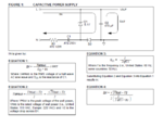
I want to design transformer less power supply which can provide 12 v and 40 mA current.

I have tried the circuit (image attached) but the AC Voltage drops to 4.5 after the capacitor and the output voltage is about 2.5 V.

My circuit has different components values than shown in the diagram.

My values:

R1 = 2.7 ohms
C1 = 1.25uf , 400 V
D1 = 12 V
C2 = 470 uf

Input AC Voltage is 220 V,50 Hz

How to get 12 V DC output? Capture.PNG
 

Dear w_bwr
Hi
I don't suggest you this circuit, because it is not isolated and it is pretty dangerous . but if you made your choice, i just can help you ! increase the zener voltage . it would has enough effect !
Best Wishes
Goldsmith
 

increase the zener voltage . it would has enough effect !

Zener Voltage is already 12 V but i am getting 2.5 v DC output.
Shouldn't it be 12 v or i still need to increase zener voltage?
 

How much is the value of RL ?

Load is a 100 ohm Relay.

Input AC Voltage = 220V, 50Hz
AC Voltage after C1 drops to 2.3 V.
DC Voltage across relay is 1.5v

Q1: I connected R1 & C1 in Phase line instead of neutral and changed the diodes polarity accordingly. Does this matters?

Q2: How does a Capacitor is able to drop AC Voltage. What is the theory behind it.

Q3: (The most important) How can i get 12 v DC output?
 

1st: 12v/100ohm = 0.12 A = 120 (and NOT 40) mA relay current !!

2nd: the value of R1 (now 2.7ohm) is too small, use min. 220ohm here (to decrease max. current peak!!)

3rd: always use an additional R2 resistor (for ex. a 470kohm) parallel to C1 to avoid an unwanted shock

4th: the value of C1 (now 1.25uF ) is also small for the wanted 120 mA load current, use a 2uF or larger, min. 400v !!

----------
An approximate calculation for C1 (120 mA load):

Xc = 1 / (2*pi*f*C) ............... C = 1/ (2*pi*50*Xc)
and
0.12 A = (220volt) /Xc .......... Xc = 220/0.12 (ohm)
so
C = 0.12 / (220*2*pi*50) = 1.74e-6 Farad = 1.74 uF

( if I were calculated well :-| )
zuisti
 

I am not getting 12 v DC output.

It gives 3.5 DC output. How to get 12v DC output..
 

C = 0.12 / (220*2*pi*50) = 1.74e-6 Farad = 1.74 uF ( if I were calculated well :-| )

This is ok. for full wave rectification. But here half wave rectification is used, so he'll need at least 2.5µF .

R1 = 220Ω / ≧2W
D1 = 13V (in order to get Vout=12V)
 

Tried the 13V Zener, still didn't get 12 v output.
I have pcb which same capacitor and resistor for power supply. Voltage after C1 is 12 v on pcb.
but when i draw the same circuit on the bread board. Voltage after C1 drops to 3.5 v. What could be the problem?
I can do all the current and power calculation afterwords.
 

Hello,

I use a circuit like this as switch - on delay for torodial transformers, but with bridge rectifier. **broken link removed**

The resistor R1 is to discharge C1 after disconnecting from line to avoid elektric shocks.

D1 prevents C2 for high voltage, if the relais coil has a fault.

I hope tis will help you.

Best regards

Rainer

PS: Sorry, if my English is not so good
 

I use a circuit like this as switch - on delay for torodial transformers, but with bridge rectifier. Here you can see my circuit.

tried this circuit, but my voltage after capacitor drops to 2.5 v not 13 volts.

- - - Updated - - -

I have pcb in which 1uF 400 volts capacitor is connected for the power supply and it voltage after capacitor is 12 v.

When i use the same capacitor on bread board, it gives 2.5 v output. I also tried trying a new capacitor but the problem is the same.
 

This is ok. for full wave rectification.....

Hi erikl; You're right. Forgotten the half-wave rectifying. Sorry and thanks!

:wink: Although it is possible that it is also working because a relay hold voltage can be much smaller than its switch-on voltage :wink:

@w_bvr
You may have a faulty component on breadboard :-|
 

Hello w_bwr,

I think, you have a fault in one of your devices. Everytime you write, that you have 2,5V at C1. Can it be, that the Zenerdiode has the wrong polarisation or that there is a short circuit? Maybe the C2?

Best regards

Rainer
 

:wink: Although it is possible that it is also working because a relay hold voltage can be much smaller than its switch-on voltage :wink:

Hi zuisti,

you're absolutely right for holding the "on" state, but what about achieving it? Of course a 12V relay could switch on with already - say - 9V if the necessary current can be delivered, but there's no safety margin. Quite ok. for an individual tinker toy, but not for a real application, I'd say.

Anyway, this potentially dangerous HV application should be totally encased in plastic, still allowing for enough cooling of the ≈3W power consumption of R1, D1 (& D2).
 

The layout in post #1 ought to work as described, theoretically.

I calculate a load of 300 ohms, in order to draw 40 mA at 12V.

There is surge current on power-up. If the zener is not rated to withstand the surge then it can be ruined. In any case it ought to be tested out of circuit.

Below is a link to an animated simulation. It will open the falstad.com website. Click OK to load the Java applet. Five moving scope traces tell what's going on.

You can alter a component by right-clicking on it, Choose Edit or any other menu command. (On a Mac use Control-click.)

https://www.falstad.com/circuit/#$+...0+35+20.0+0.8+3+-1 o+5+64+0+35+20.0+0.8+4+-1
 
  • Like
Reactions: zuisti

    zuisti

    Points: 2
    Helpful Answer Positive Rating
Thanks All.

My C2 was damaged.

I have made little changes to the layout mentioned in post #1 .

Capture.PNG

This works fine.
 

Status
Not open for further replies.

Similar threads

Part and Inventory Search

Welcome to EDABoard.com

Sponsor

Back
Top