Continue to Site

Welcome to EDAboard.com

Welcome to our site! EDAboard.com is an international Electronics Discussion Forum focused on EDA software, circuits, schematics, books, theory, papers, asic, pld, 8051, DSP, Network, RF, Analog Design, PCB, Service Manuals... and a whole lot more! To participate you need to register. Registration is free. Click here to register now.

[SOLVED] Problems with 16 x 1 lcd display

Status
Not open for further replies.

misooo13

Newbie level 3
Joined
Jun 26, 2012
Messages
3
Helped
0
Reputation
0
Reaction score
0
Trophy points
1,281
Activity points
1,304
Hi! I have a 16 x 1 display ATM 1601a ns bbw. My first problem was that only the first 8 characters were visible. I solved this problem by cofiguring display as 2 lines display 2 x 8 characters. But now I have problem with visibility of the characters. When configured as 1 line display the characters were white with blue background. Now, as 2 lines display, I can hardly read the characters, the background is still blue, but the characters are not white, they are grey and almost cannot be seen. Can you help me with this? Thank you in advance
 

Hi,

Welcome to the forum.

From what I read in the datasheets of that display and its controller it should simply display the 16 characters as one row starting at address 00.

Cannot explain your happenings with 2x8 etc, but would suggest there is something wrong with your wiring or you program code - its easily done.

Do first check your connections to the lcd, its so easy to either get the wrong pin or short two pins with a wisker of solder - we have all done it !

If you still have problems, then post your source code and a diagram, then we can try and see where things are going wrong.
If you can post a photo of your build as well that helps.
Also mention what programs/compliers/ micro you are using.
 

This is a common problem when changing from one line to two line display, when you change to two line display you need to alter the contrast control. If you haven't fitted a contrast control you will need to do so. A contrast control can be as simple as connecting a 5k pot from pin 3 to ground.
 
Thank you both for interest.
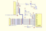
pjmelect: I will try this, I think this could solve my problem with the visibility of characters. I can try it on friday. I am attaching you the connection of the display, I think there is problem with the R13 resistance.

wp100: I don't have the source code right now, I can send it on friday if the problem will still be there. I am using PIC microprocessor and MPLAB IDE.


LCD_connection.jpg
 

Hi,

Thr cicuit looks basically sound, as pmjelect says a 5K or 10k trimmer / pot is normally used instead of R13 /R14, this allows you to have total control over the contrast.
The slider is taken to Vo on the lcd with the pots outer connections to Vss and Vdd respectively
 
A fixed divider in the contrast circuit is not good enough, the adjustment for optimal contrast and speed of response time is critical. When operating the display as a one line (8 characters) the contrast control is not as critical as it is operating as two lines (16 characters). This is normal behavior for this type of LCD display.
 
Thank you so much, both of you. We removed the R13 resistance and the display was bright and readable. So we tried several resistances, and adjusted for optimal contrast.
 

Status
Not open for further replies.

Similar threads

Part and Inventory Search

Welcome to EDABoard.com

Sponsor

Back
Top