Jestin_cubetech
Advanced Member level 1
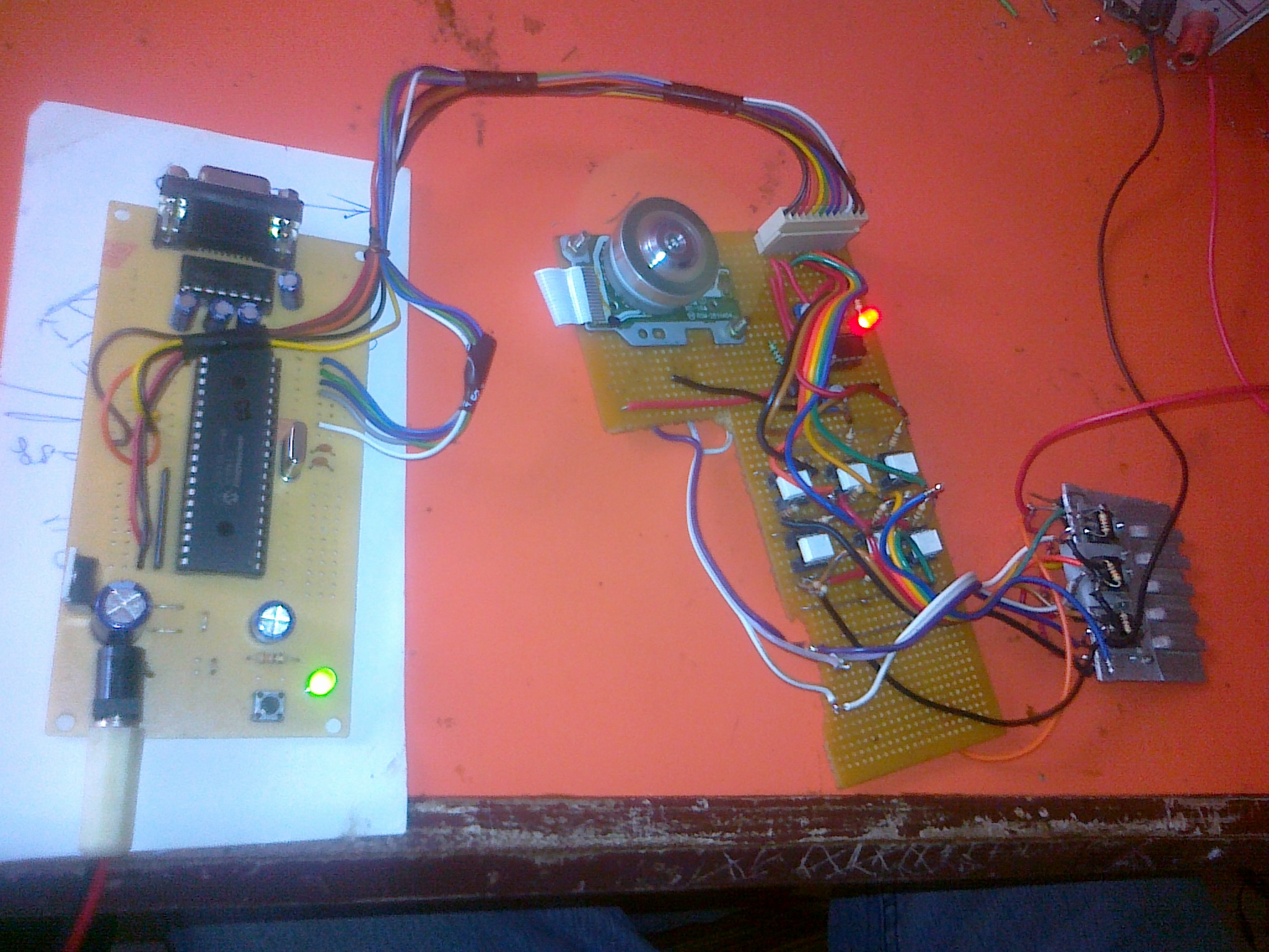
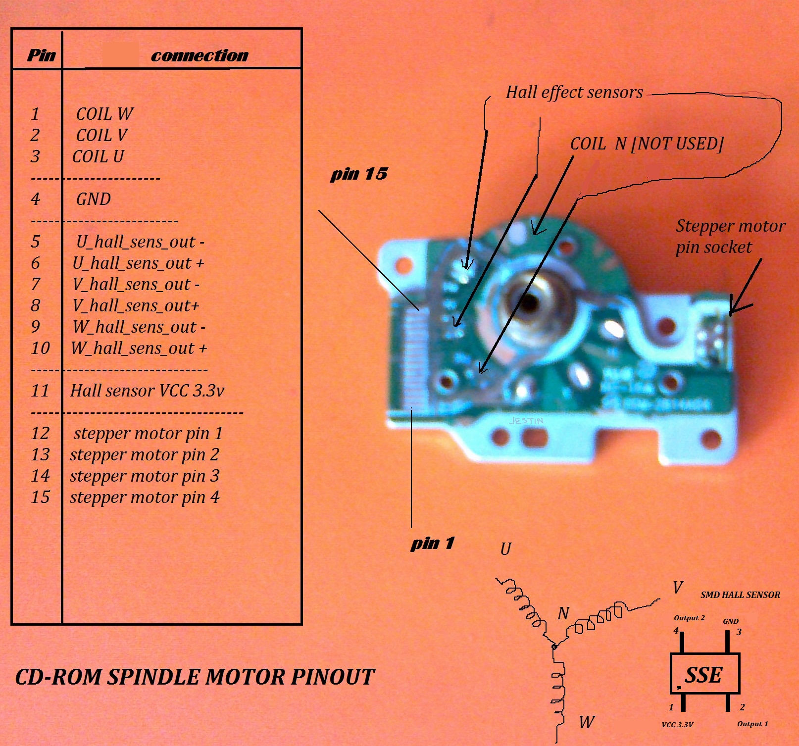
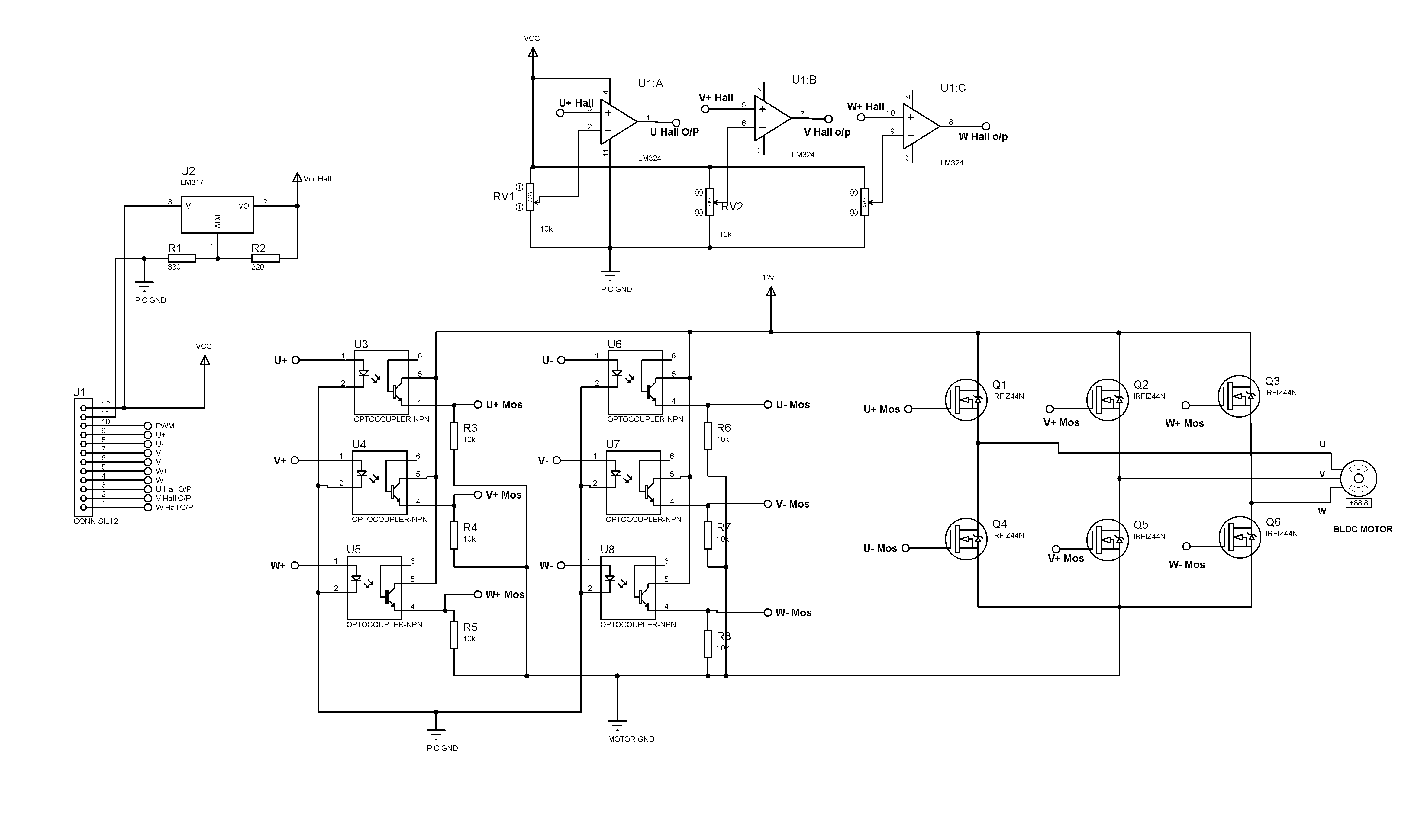
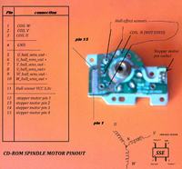
Hall Sensor Based BLDC Motor driving using microcontroller.

Code:
#include <pic.h>                         //BLDC DRIVER  delta connection and hall sensor
#define _XTAL_FREQ 20000000
unsigned char n=0,hall_sens=0,k=0;
bit DIR;
const unsigned char commutation[12][2]=
{
//---------------forward----------
 0x80,0x24,//10.01.00 0x31,//
 0xa0,0x06,//00.01.10 0x1F,//
 0x20,0x12,//01.00.10 0X07,//
 0x60,0x18,//01.10.00 0X0D,//
 0x40,0x09,//00.10.01 0X1C,//
 0xc0,0x21,//10.00.01 0X34,//
 //---------------Reverse---------
 0x80,0x18,//0X0D,//
 0xc0,0x12,//0X07,//
 0x40,0x06,//0X1F,//
 0x60,0x24,//0X31,//
 0x20,0x21,//0X34,//
 0xa0,0x09,//0X1C,//
};

void motor_startup()
{
 RBIE=0;GIE=0;
 PORTD=0x24;
 __delay_ms(10);
 PORTD=0x06;
 __delay_ms(10);
  PORTD=0x12;
 __delay_ms(10);
  PORTD=0x18;
 __delay_ms(10);
  PORTD=0x09;
 __delay_ms(10);
  PORTD=0x21;
 __delay_ms(10);
 RBIE=1;GIE=1;
}
////////////////////////////////////////
void motor_stop()
{
 PORTD=0;
 RBIE=0; RBIF=0;GIE=0;
 PORTD=0;
__delay_ms(10);
 RBIE=0; RBIF=0;GIE=0;
 PORTD=0;
}
void interrupt isr()
{
 	if(RBIF)
      {
         RBIF=0;
         hall_sens=(PORTB&0Xe0);	// HALL EFFECT SENSOR READING

if(DIR)   //FWD
{
         for(n=0;n<5;n++)
        {
         if(hall_sens==commutation[n][0]){k=n;}
        }
}
else    //BWD
{
        for(n=5;n<11;n++)
        {
         if(hall_sens==commutation[n][0]){k=n;}
        }
}
        PORTD=(commutation[k][1]&0X3F);
      }
}

////////////////////////////////////////
void main()
{
     TRISD=0x0;PORTD=0;TRISB=0xF0;
     TRISA=0x01; ADCON1=0x80;   LED=1;
    RBIE=0;RBIF=0;

 PEIE=1;GIE=1;
motor_startup();
while(1);

}