Continue to Site

Welcome to EDAboard.com

Welcome to our site! EDAboard.com is an international Electronics Discussion Forum focused on EDA software, circuits, schematics, books, theory, papers, asic, pld, 8051, DSP, Network, RF, Analog Design, PCB, Service Manuals... and a whole lot more! To participate you need to register. Registration is free. Click here to register now.

Controlling a DC motor 12 V using PWM and two relays

Status
Not open for further replies.

Cristinuk

Newbie level 3
Joined
Jun 22, 2012
Messages
3
Helped
0
Reputation
0
Reaction score
0
Trophy points
1,281
Activity points
1,343
I'm trying to control a dc motor(12 V) with two relays by using PWM. I've made the program(in MicroCfor PIC,because I'm using a PIC16F877A microcontroller) and the simulation in ISIS Proteus.
I have a problem, the motor doesn't run continously,it stops,then it starts again. I think it's something with PIC's frequency but I can't find the problem.
I've set the PWM frequency at 300 Hz...if I put it bigger,it doesn't work at all.The external crystal is set at 4 MHz.
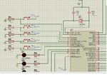
I've attached also a picture with the simulation.

Here's the code:


Code C - [expand]
1
2
3
4
5
6
7
8
9
10
11
12
13
14
15
16
17
18
19
20
21
22
23
24
25
26
27
28
29
30
31
32
33
34
35
36
37
38
39
40
41
42
43
44
45
46
47
48
49
50
51
52
53
54
55
56
57
58
59
60
61
62
63
64
65
66
67
68
69
70
71
72
73
74
75
76
77
78
79
80
81
82
83
84
85
86
87
88
89
90
91
92
93
94
95
96
97
98
99
100
101
102
103
104
105
106
107
108
109
110
111
112
113
114
115
116
117
118
119
120
121
122
123
124
125
126
127
128
129
130
131
132
133
134
135
136
137
138
139
140
141
142
143
144
145
146
147
148
149
150
151
152
153
154
155
156
157
158
159
160
unsigned short current_duty, current_duty1;
 
void InitMain() {
  ADCON1=7;                         //Configure pins as digital
  CMCON=0x07;                      //Disable comparators
  PORTA.RA0 = 0xff;
  PORTA.RA1 = 0xff;
  PORTA.RA2 = 0xff;
  PORTA.RA3 = 0xff;
  PORTA.RA4 = 0xff;
 
 
  TRISA.RA0 = 1;
  TRISA.RA1 = 1;
  TRISA.RA2 = 1;
  TRISA.RA3 = 1;
  TRISA.RA4 = 1;
 
  TRISA.RA5 = 0;
  TRISE.RE0 = 0;
  TRISE.RE1 = 0;
  TRISE.RE2 = 0;
  TRISC.RC0 = 0;                          // designate PORTC pins as output
 
  TRISC.RC1 = 0;
  TRISC.RC2 = 0;
  TRISC.RC5 = 0;
  TRISC.RC6 = 0;
  TRISC.RC7 = 0;
  TRISD.RD0 = 0;
  TRISD.RD1 = 0;
  TRISD.RD2 = 0;
  TRISD.RD3 = 0;
  TRISD.RD4 = 0;
  TRISD.RD5 = 0;
  TRISC.RC1 = 0;
 
  TRISB.RB0 = 1;
  TRISB.RB1 = 1;
  TRISB.RB2 = 1;
 
 // PORTB.RB0 = 0xff;
 // PORTB.RB1 = 0xff;
 // PORTB.RB2 = 0xff;


  PWM1_Init(300);                    // Initialize PWM1 module at 300Hz
  PWM2_Init(300);                    // Initialize PWM2 module at 300Hz
 
 
}
 
void main() {
  InitMain();
  current_duty  = 0;                 // initial value for current_duty
  current_duty1 = 0;
 
 
   PWM1_Start();
   PWM2_Start();                       // start PWM1
   PWM1_Set_Duty(current_duty);        // Set current duty for PWM1                   // start PWM1
   PWM2_Set_Duty(current_duty1);        // Set current duty for PWM1
 
  PORTA.RA5 = 0xff;
  PORTE.RE0 = 0xff;
  PORTE.RE1 = 0xff;
  PORTE.RE2 = 0xff;
  PORTC.RC0 = 0xff;
 
  PORTC.RC5 = 0x00;
  PORTC.RC6 = 0x00;
  PORTC.RC7 = 0x00;
  PORTD.RD0 = 0x00;
  PORTD.RD1 = 0x00;
  PORTC.RC1 = 0x00;


  while (1)                          // endless loop
  {
    if (RA0_bit)                     // button on RA0 pressed---> first place from the parking
            {  PORTA.RA5=0x00;
               PORTC.RC5=0xff;
               PORTD.RD2=0x00;
               PORTD.RD3=0x00;
               current_duty=current_duty+1;                 // increment current_duty
               PWM1_Set_Duty(current_duty);
            }
 
    // touching the first microlimitator-----> decrease speed
     if (RB1_bit)
      {     PORTD.RD2=0x00;
            PORTD.RD3=0x00;
            current_duty=current_duty-1;                 // decrement current_duty
            PWM1_Set_Duty(current_duty);
      }
      //touching the second microlimitator----> motor stops
       if (RB2_bit)
         { PWM1_Stop();
           PORTC.RC2=0x00;
         }
 
    if (RA1_bit)                     // button on RA1 pressed -----> second place of parking
        { PORTE.RE0=0x00;
          PORTC.RC6=0xff;
          PORTD.RD2=0xff;
          PORTD.RD3=0xff;
          current_duty1=current_duty1+1;                 // increment current_duty
          PWM2_Set_Duty(current_duty1);
         }
 
     if (RB4_bit)
 
        {   PORTD.RD2=0xff;
            PORTD.RD3=0xff;
            current_duty1=current_duty1-1;                 // decrement current_duty
            PWM2_Set_Duty(current_duty1);
        }
 
      //touching the second microlimitator----> motor stops
       if (RB6_bit)
         { PWM2_Stop();
           PORTC.RC2=0x00;
         }
 
     if (RA2_bit)        // button RA2 pressed-touching the third place of parking
        { PORTE.RE1=0x00;
          PORTC.RC7=0xff;
          PORTD.RD2=0x00;
          PORTD.RD3=0x00;
          current_duty=current_duty+1;
          PWM1_Set_Duty(current_duty);
         }
 
     if (RA3_bit)        //button RA3 pressed -touching the fourth place of parking
     {
       PORTE.RE2=0x00;
       PORTD.RD0=0xff;
       PORTD.RD4=0x00;
          Delay_ms(3000);
          PORTD.RD5=0x00;
          Delay_ms(2000);
          PORTD.RD5=0xff;
          PORTD.RD4=0xff;
     }
     if (RA4_bit)          //-touching the fifth place of parking
 
       // if (current_duty1<250)
        { PORTC.RC0=0x00;
          PORTD.RD1=0xff;
          PORTD.RD2=0xff;
          PORTD.RD3=0xff;
          current_duty1=current_duty1+1;
          PWM2_Set_Duty(current_duty1);
        }
 
 
  }
 }


prog.jpgprog.jpg
 
Last edited by a moderator:

Unfortunately your code is unreadable, can you format it? Otherwise we have to follow every curly bracket and count them up and down.
Also, PWM with relays is not really a good idea, and may be causing the issues. You should switch to some semiconductor method (e.g. MOSFETs).
 

It was my teacher's idea :(

Here's the code simplified:

Important: Motor runs in one way when both relays are off and in the other way when are both on.Pins RD2 and RD3 are for these relays,as in the simulation.


Code C - [expand]
1
2
3
4
5
6
7
8
9
10
11
12
13
14
15
16
17
18
19
20
21
22
23
24
25
26
27
28
29
30
31
32
33
34
35
36
37
38
39
40
41
42
43
44
45
46
47
48
49
50
51
52
53
54
55
56
57
58
59
60
61
62
63
unsigned short current_duty, old_duty, current_duty1, old_duty1;
 
void InitMain() {
  ADCON1=7;                         //Configure pins as digital
  CMCON=0x07;                      //Disable comparators
  TRISA.RA0=1;
  TRISA.RA1=1;
  TRISB.RB0=1;
  TRISB.RB1=1;
  TRISB.RB2=1;
 
  TRISD.RD2=0;
  TRISD.RD3=0;


  PWM1_Init(300);                      // Initialize PWM1 module at 300Hz
  PWM2_Init(300);                      // Initialize PWM2 module at 300Hz
 
void main() 
{
  InitMain();
  current_duty  = 0;                   // initial value for current_duty
  current_duty1 = 0;
 
 
   PWM1_Start();                       // start pwm1
   PWM2_Start();                       // start PWM2
   PWM1_Set_Duty(current_duty);        // Set current duty for PWM1                   
   PWM2_Set_Duty(current_duty1);       // Set current duty for PWM1
 
while (1)                              // endless loop
  {
    if (RA0_bit)                       //  when button  RA0 is pressed, the motor starts in one way
            {  PORTA.RA5=0x00;         //turn off the green led
               PORTC.RC5=0xff;         //turn on the red led
               PORTD.RD2=0x00;      
               PORTD.RD3=0x00;
               current_duty=current_duty+1;                 // increment current_duty
               PWM1_Set_Duty(current_duty);
            }
 
    if (RB1_bit)                            // when button RB1 is pressed , the speed of the motor should decrease
      {     PORTD.RD2=0x00;             
            PORTD.RD3=0x00;
            current_duty=current_duty-1;                 // decrement current_duty
            PWM1_Set_Duty(current_duty);
      }
      
       if (RB2_bit)                         // when RB2 is pressed, the motor should stop
         { PWM1_Stop();
           PORTC.RC2=0x00;
         }
 
      if (RA1_bit)                     // button on RA1 pressed -----> motor should run on the other way
        { PORTE.RE0=0x00;            //turn off the green led
          PORTC.RC6=0xff;            //turn on the red led
          PORTD.RD2=0xff;            //the relays are activated 
          PORTD.RD3=0xff;
          current_duty1=current_duty1+1;                 // increment current_duty
          PWM2_Set_Duty(current_duty1);
         }
}

 
Last edited by a moderator:

Sorry, your code is still unreadable. You should click on the '#' symbol on this forum when adding code, so that it appears like:
Code:
this.
Anyway, I think the two relays are to switch direction, and transistor Q3 is to be fed with a PWM signal? If so, why are you using two
PWMs in the code? Only Q3 should be fed with a PWM signal. Where are you sending the two PWM signals currently? Also, your
circuit diagram is too small to read much : (
 

You are absolutely right, I have fixed the error.

The final code is:
Code:
unsigned short current_duty;

void InitMain() {
  ADCON1=7;                         //Configure pins as digital
  CMCON=0x07;                      //Disable comparators
  TRISA.RA0=1;
  TRISA.RA1=1;
  TRISB.RB0=1;
  TRISB.RB1=1;
  TRISB.RB2=1;

  TRISD.RD2=0;
  TRISD.RD3=0;


  PWM1_Init(300);                      // Initialize PWM1 module at 300Hz

void main() 
{
  InitMain();
  current_duty  = 0;                   // initial value for current_duty


   PWM1_Start();                       // start pwm1
   PWM1_Set_Duty(current_duty);        // Set current duty for PWM1                   


while (1)                              // endless loop
  {
    if (RA0_bit)                       //  when button  RA0 is pressed, the motor starts in one way
            {  PORTA.RA5=0x00;         //turn off the green led
               PORTC.RC5=0xff;         //turn on the red led
               PORTD.RD2=0x00;      
               PORTD.RD3=0x00;
               current_duty=current_duty+1;                 // increment current_duty
               PWM1_Set_Duty(current_duty);
            }

if (RB1_bit)                            // when button RB1 is pressed , the speed of the motor should decrease
      {     PORTD.RD2=0x00;             
            PORTD.RD3=0x00;
            current_duty=current_duty-1;                 // decrement current_duty
            PWM1_Set_Duty(current_duty);
      }
      
       if (RB2_bit)                         // when RB2 is pressed, the motor should stop
         { PWM1_Stop();
           PORTC.RC2=0x00;
         }

    if (RA1_bit)                     // button on RA1 pressed -----> motor should run on the other way
        { PORTE.RE0=0x00;            //turn off the green led
          PORTC.RC6=0xff;            //turn on the red led
          PORTD.RD2=0xff;            //the relays are activated 
          PORTD.RD3=0xff;
       
         }
   }
}

But the motor still doesen't work well:(

pic1.jpgpic2.jpg

I've also attached two other pictures with the simulation.
 

Sorry, I don't know the problem. Maybe your PMW1_Set_Duty function (I can't see it) doesn't like being set repeatedly in a while loop.
I'm not familiar with MicroC.

You should start of with some very simple code, make it work, and then slowly build up to the final code.
 

WITHOUT reading your very complicated code, and WITHOUT looking at your very complicated circuit (which I think could be much simplified), here's my suggestion....

Power the main DC voltage (using PWM or direct) using a single BJT/ MOSFET/ whatever floats your boat, activated by your uC signal.
Switch your relays using a single output line from your uC, with an inverter in between. A simple BJT for the inverter will suffice.

REVIEW your circuit diagram AND your final breadboard/ PCB for obvious mistakes. Follow the various signals to see if they make sense, and seem to work like you planned.
Cross-check that all your specifications are within design limits. E.g. Relay cut-in voltage etc including BJT C-E voltage drops.

I see no reason why a 300Hz PWM will not work. It may produce an annoying sound from the motor, but it will work.

And finally, Check that your duty cycle is not so low that it cannot overcome the initial friction/ inertia of the motor. Some motors need a bigger kick-in-the-pants to start working.

Lastly of course, if it works in ONE direction but not the other, then obviously some of your Relays/ Direction control signals are messed up. Check those ...

cheers!
:)
 

Your relay may be not enough fast to handle a 300Hz PWM. As it have been said, try yo switch to MOSFET or JFET semiconductor. 1/300Hz = 3.3ms I don't know what kind of relay your are using but i wonder if they can handle this speed.

I know its your teacher ideal but it is not a good one because event if it work...it is not the good way to do it because you will break your relay in 1 hr of use.

300Hz = 300 clic/sec
300clic * 60sec * 15min = 1 080 000 clic. Some small relay can handle only 1 000 000 clic.

Hmmm... the relays do NOT 'relay' the PWM @300Hz. They relay only the direction of rotation, which is much much much much slower than that.
Try and not do silly calculations where they are not relevant.... yes FboDigit ?

cheers!
:)
 

Hmmm... the relays do NOT 'relay' the PWM @300Hz. They relay only the direction of rotation, which is much much much much slower than that.
Try and not do silly calculations where they are not relevant.... yes FboDigit ?

cheers!
:)

...I read my post like 5 times and I don's see when i sais that the relays are relaying (lol)
You r right about the rotation..I took a look at the circuit too fast..my bad.

But those calculation are still correct if you want to make a PWM with relays (still a very bad ideal)
 

...I read my post like 5 times and I don's see when i sais that the relays are relaying (lol)
You r right about the rotation..I took a look at the circuit too fast..my bad.

But those calculation are still correct if you want to make a PWM with relays (still a very bad ideal)

Of course your calcs are correct Fbo... !! Just saying that they aren't relevant here. And of course I agree its a bad design to use a relay for continous 300Hz toggling. In fact, in this case since its a PWM signal, its even worse, since the ON-OF-ON rates make be a fraction of 3mS, and the relay will not even work for many duty-cycle ratios !!

cheers bro ! ;-)
 

Status
Not open for further replies.

Part and Inventory Search

Welcome to EDABoard.com

Sponsor

Back
Top