nooobboy4321
Junior Member level 1
Hello Everyone, I have questions about Microcontrollers. So lets start with...
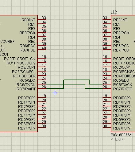
1. How to connect a 2 PIC16F877A using UART?
2. Is there a need of MAX232 to execute this? like a bridge for 2 MCU's??
3. I'm not sure if my codes are correct...I'm using MikroC Pro and ISIS for simulations.
I'm building a simple idea about toggling LED. This is my codes:
:::::MCU1:::::
and here's the other one....
:::::MCU2:::::
Heres a simple graphical representation of my idea...
Thanks in advance....
1. How to connect a 2 PIC16F877A using UART?
2. Is there a need of MAX232 to execute this? like a bridge for 2 MCU's??
3. I'm not sure if my codes are correct...I'm using MikroC Pro and ISIS for simulations.
I'm building a simple idea about toggling LED. This is my codes:
:::::MCU1:::::
Code:
void main() {
TRISB = 0xFF;                                     // Set B as Input
PORTB = 0x00;                                     // Set B to FF

UART1_Init(9600);                                // MCU1 Baudrate
Delay_ms(100);

              do {
              if (RB0_bit)                           // If RB0 is Toggled
              UART1_Write_Text("A");          // Send Info From MCU1 Toggled RB0 to MCU2
              Delay_ms(1000);
              PORTB = 0x7E;                      // Toggle RB1-RB6
              if (RB1_bit)
              UART1_Write_Text("B");          // Send Info From MCU1 Toggled RB1 to MCU2
              Delay_ms(1000);
              PORTB = 0xFC;                      // Toggle RB2-RB7
              } while (1);
}
and here's the other one....
:::::MCU2:::::
Code:
char dfmcu1;            // Variable: Data From MCU1

void main() {
TRISB = 0x00;                    // Set B as Output
PORTB = 0x00;                    // Set B to OFF


UART2_Init(9600);                // MCU2 Baudrate
Delay_ms(100);

              do {
                 if (UART2_Data_Ready())    // Waiting for the data from MCU1
                 dfmcu1 = UART2_Read();     // Read
                 UART2_Write(dfmcu1);       // Container dfmcu1
                 Delay_ms(100);
                 if (dfmcu1 == 0x41)        // if d' data receive is A
                 PORTB = 0x7F;              // RB0-RB6 will Toggle
                 if (dfmcu1 == 0x42)        // if d' data receive is B
                 PORTB = 0xFE;              // RB1-RB7 will Toggle
                 } while (1);
}
Heres a simple graphical representation of my idea...
Thanks in advance....
Attachments
Last edited by a moderator: