viperpaki007
Full Member level 5
Hi,
Can any body explain how the positive and negative edge triggered flip-flop works in the following link
**broken link removed**
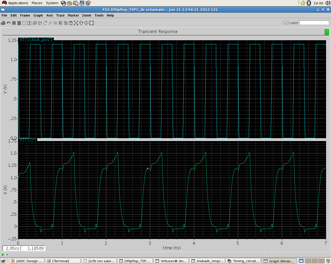
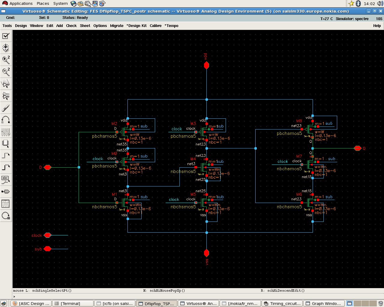
I have made the same flip flop (as divider) in cadence in 130nm process for high speed operation but the simulation results show a voltage glitch at the output. I don't know what is the reason for that. Screen shots of results are attached.
Clock frequency 2GHz
Rise time 25ps
Fall time 25ps
Supply voltage 1.2V
Can any body explain how the positive and negative edge triggered flip-flop works in the following link
**broken link removed**
I have made the same flip flop (as divider) in cadence in 130nm process for high speed operation but the simulation results show a voltage glitch at the output. I don't know what is the reason for that. Screen shots of results are attached.
Clock frequency 2GHz
Rise time 25ps
Fall time 25ps
Supply voltage 1.2V