Continue to Site

Welcome to EDAboard.com

Welcome to our site! EDAboard.com is an international Electronics Discussion Forum focused on EDA software, circuits, schematics, books, theory, papers, asic, pld, 8051, DSP, Network, RF, Analog Design, PCB, Service Manuals... and a whole lot more! To participate you need to register. Registration is free. Click here to register now.

how to operate an l.e.d.from 230 volts 5mA 50 cycles per second a.c. power source

Status
Not open for further replies.

rajaram04

Advanced Member level 3
Joined
Jun 17, 2012
Messages
871
Helped
6
Reputation
12
Reaction score
5
Trophy points
1,298
Location
earth
Activity points
7,687
Hello sir

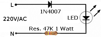
I simply want to operate a single blue or green l.e.d. by means of 230v a.c. source without using any condenser so get me a simple circuit diagram without complications & easy to implant within a small pin plug.I made one with a single green l.e.d. in series with 100k resistor but the l.e.d. was damaged in two days :( so please help me
Thanks
 

I made one with a single green l.e.d. in series with 100k resistor but the l.e.d. was damaged in two days
You apparently forgot a rectifier diode or bridge rectifier.
 

You have to protect the LED in the reverse polarity so you can either connect a diode in series or an anti parallel diode on the LED
 

I take it the supply is 230V RMS mains?

If you just put an led in series with a resistor, the led has to withstand a peak reverse voltage of: (230V + 10%) x sqrt(2) = 358V. It won't...

Put a high-voltage diode in series with the LED. Put another high-voltage diode in parallel with the LED but reversed (diode K to led A, diode A to led K).

The series diode stops the circuit conducting current during negative mains half-cycles. This halves the power dissipated in the series resistance (see 0.5 in resistor power calculations below).

The parallel diode clamps the excessive reverse voltage across the led in negative half-cycles. This is caused by leakage current through the series diode and will destroy the led.

Use at least a 400V diode for these (e.g. 1N4007 if you've got the space).

That leaves the resistor, dissipating power of: 230 x 0.005 x 0.5 = 575 mW. A single resistor can theoretically fail short-circuit, in a safety standard body's view anyway, so definitely use at least two resistors to design this weakness out. If one fails, the other(s) still limit the current though they dissipate more power.

Series resistance required is: 230V/.005 = 46K.

Using two 22K resistors, total power in one when the other is shorted is: 230*230*0.5/22000 = 1.2W. Derating by around half means use two 2W resistors.

Using four 12K resistors, total power in each when one is shorted is: (230*230*0.5/36000)/3 = 735mW. Derating by around half means use four 1.5W resistors. But you could go with four 1W resistors and still have derating of a third.

Remember that this watt or so in the series resistors needs air to dissipate into. Otherwise it'll break again over time. And if you can, use a 1mA led instead of a 5mA led to considerably reduce the power in the resistors.

To meet electrical safety standards, users must be separated from mains power by double insulation i.e. two layers of insulation. The led plastic body is only one, so put something like a transparent bezel over it.

Hope this helps.
 
Last edited:

okk sir the expalin is nice to me i mean its just wowww but could you please let me have that circuit diagram you are telling me here above ? As it is concerned with a.c. source so i don't want to take risk as there is a major diffrence in what we studied & what practically we find :) so please a sketch of that i want here sir help me :)

- - - Updated - - -

sir also tell me the value of high voltage diode diode to be used here please sir cause i didn't find any 400 v range IN4007 diode :( now what to do sir ?
 
Last edited:

I'm sure it's possible, if don't want to burn so much power, to use a few transistors that connect the line and charge up a capacitor (which is parallel with the LED) and turn off when the voltage gets too high.
 
  • Like
Reactions: FvM

    FvM

    Points: 2
    Helpful Answer Positive Rating
Yes, that's an interesting and valid idea :)

But for something mains powered, that's got to work reliably and safely for years, I would personally stick with the circuit I'd described though. Less to go wrong, simple failure modes.

Not discrediting your suggestion though, these ideas that expand our thinking are the point of the forum :)
 

I'm sure it's possible, if don't want to burn so much power, to use a few transistors that connect the line and charge up a capacitor (which is parallel with the LED) and turn off when the voltage gets too high.
I think, charging a capacitor through a transistor or resistor doesn't reduce power dissipation compared to a simple series resistor.

For a higher efficiency voltage conversion, you'll need either an inductive switch mode converter or multi-stage charge pump. According to the initial post, we can exclude this solution class.

Using a bridge rectifier instead of a single diode however doubles effciency respectively halves power dissipation. A small SMD bridge consumes less space than using a double size power resistor. For minimal part count you can use a dual chip bidirectional LED, which can be operated with just a series resistor.
 

I think, charging a capacitor through a transistor or resistor doesn't reduce power dissipation compared to a simple series resistor.

Actually, I was envisioning a circuit which switches the transistor on only when the AC line voltage is low and turns off when the AC line is high (i.e., phase angle commutation) so that the transistor is never dissipating lots of power. You couldn't brag about your power factor or harmonics, but with power levels this low nobody would complain.
 

ok sir i am planning to use two 22 k resistor of 2 watts as per your suggestion so what you say on it ? may i proceed ?
 

Replying to FvM earlier today...

I took the ZekeR suggestion to be: at zero-crossing, switch a transistor on to charge a cap until the mains is at (say) 20V. Switch transistor off and power led from cap while mains rises and falls back to zero. A single-transistor constant-current circuit would pass capacitor current to the led in the meantime. Power dissipation is very low. Circuit is more complicated but not hugely.

The bridge rectifier is suggested to increase efficiency, but the target here isn't efficiency. It's low power dissipation and simplicity. My single-phase suggestion needs a capacitor across the led to reduce mains frequency flickering but single phase has to be better than maximum energy out of the supply and into a dropper resistance...?

Food for thought, I'm sure :)
 
  • Like
Reactions: FvM

    FvM

    Points: 2
    Helpful Answer Positive Rating
i didn't find any 400 v range IN4007 diode :( now what to do sir ?
You can use one of these circuits. They do not need high voltage diodes. Any small diode e.g. 1N4148 will be OK.


As tony explained, it may be safer to use a few resistors in series.
 
  • Like
Reactions: FvM

    FvM

    Points: 2
    Helpful Answer Positive Rating
I designed and simulated this circuit. 3 transistors, two diodes, 4 resistors, and two capacitors (which are required to stand off < 20V). My simulator claims that 100mW is drawn from the power supply (10mW is delivered to the LED, 50mW is in R5, and the remaining 40mW is split between R1 and M1). Another cool thing: it works on 120V 60Hz too!

Of course, you'd want to build and test it to make sure it works. I'm curious to see if anybody comes up with a better (i.e., cheaper but still low power) circuit, and what weaknesses my circuit has. =)

Hope this helps

LowPowerOfflineLED.png
 
  • Like
Reactions: FvM

    FvM

    Points: 2
    Helpful Answer Positive Rating
Thanks to godfreyl for elaborating the bridge rectifier solution.

To mention the bipolar LED variant again, it can work with a part like L-937IID

Finally, the "gated" capacitor charging solution suggested by ZekeR in post #6 and detailed in post #13 can of course work. I overlocked the "turn off when the voltage gets too high" part. In a real world, the design needs to be supplemented by effective surge protection means, otherwise it would be fried by the first serious overvoltage event.
 
  • Like
Reactions: ZekeR

    ZekeR

    Points: 2
    Helpful Answer Positive Rating
You can use one of these circuits. They do not need high voltage diodes. Any small diode e.g. 1N4148 will be OK.


As tony explained, it may be safer to use a few resistors in series.

The 1N4148 has a maximum reverse voltage of 100V whereas the mains reverse voltage can be 358V, as explained above. The simple circuit you've shown relies on both diodes working to protect the other from a high reverse voltage. But if one fails, the other is seriously over-volted above its reverse voltage rating and will be damaged or destroyed. This seems like a gainless risk.

The extra components four components I described (plus the cap I missed out) will make it electrically safe and reliable to safety approval standards and give it safe failure modes. It's then an example of designing mains circuits for electrical safety. The job of such a circuit is not just to light an led at any risk for the least money.

So as engineers, I don't think it's a good thing to encourage this simple circuit onto the world. I would stick a the circuit I described or a different one with the same safety features. Just how I see it :)
 

But if one fails, the other is seriously over-volted above its reverse voltage rating and will be damaged or destroyed. This seems like a gainless risk.

In my view, this is a pointless consideration. If one part fails in a regular electronic system (e.g. any system not implementing redundancy), the whole system will most likely fail, lose it's function.

It's appropriate to use low voltage diodes for a low voltage rectifier, that's the whole story regarding the present circuit.

P.S.:There's possibly a confusion of terms. The discussion of diode failure hasn't to do with safety unless the circuit itself is required to provide functional safety in any relation. Electrical safety needs to be considered of course, but isn't affected by diode failure as far as I'm aware of.
 
Last edited:

The series connected halfwave rectifier has the disadvantage that it can't guarantee to keep the maximum LED reverse voltage. It raises the question, if the LED can stand higher reverse voltage without damage as long as the current is low (< several 10 uA specified maximum 1N400x reverse current)? It's clearly beyond LED specifications. As joke says: I can swear, but I won't bet.
 

But it's connected directly across the mains. So failures have different consequences than in a 'normal' DC/etc circuit.

It's little not much effort here to meet electrical safety requirements and it makes it a better example of how to make circuits safe. The circuit isn't being showered with extra components. An approvals body, such as BSI, would want a circuit that can safely survive a single component failure in a mains-powered circuit (they call low voltage as under 42V). Appliances around you marked with approvals will be designed to like that. They would reject the 1-diode/1-resistor instantly, I'm afraid.

The low-voltage diodes aren't being used for a low-voltage circuit though, they're being used in a high-voltage circuit. Should 358V be called 'low voltage' then? I'm sorry but I simply don't understand why it's so important to pursue using a signal diode rated at 100V, rather than a cheap and small power diode rated for the job.

Not trying to be difficult, just don't understand the objective of such an example circuit :)
 

Circuit in posted in 17 working several years for me, I didnt notice any changes on used LED, circuit is 24h on.
 

Status
Not open for further replies.

Part and Inventory Search

Welcome to EDABoard.com

Sponsor

Back
Top