Continue to Site

Welcome to EDAboard.com

Welcome to our site! EDAboard.com is an international Electronics Discussion Forum focused on EDA software, circuits, schematics, books, theory, papers, asic, pld, 8051, DSP, Network, RF, Analog Design, PCB, Service Manuals... and a whole lot more! To participate you need to register. Registration is free. Click here to register now.

Tiny Ohmmeter + some optional extras.

Status
Not open for further replies.

gppk

Newbie level 4
Joined
Oct 20, 2011
Messages
5
Helped
0
Reputation
0
Reaction score
0
Trophy points
1,281
Activity points
1,322
Hey,

So I bought myself a box of mints today and they come in a tiny little box 70mmX 25 x 15.

I wanted to see if it was possible to build a tiny ohmmeter circuit inside with these basic functionality:
  • Small Screen for Resistance
  • Switch for on/off
  • Connector for external 9v battery
  • Two connector pads to connect resistor that needs measuring

So by doing some research on ze googles i've worked out that this isn't going to be easy.

really I wanted to know how you guys would go about it. If you have used any screens that are small and easy to use.

Any help really would be great :)

Thanks.

G./
 

It would be easier to use a ceramic emitter with a current controlled one shot and let it squeal like a metal detector for short circuits and click slowly for leaky circuits and nothing when open circuit.
 

Thanks Sunny but it was the resistance values I am after, not whether they work or not.
 

That's not a bad idea. You could have 'reference' resistances to get some practise hearing the different tones.
Maybe a rotary switch with reference resistances - but small rotary switches are fairly expensive.
If you wanted to go down the display route.. try to find a small panel meter maybe? That is suitably retro, and
can look far nicer than an LCD display ; )
 

Using external battery?
:grin:
First try to consider some off the shelf products:
Cheap : DT95B Pocket Digital Multimeter
dt95b.jpg


expensive:
1. Mastech Ms8910 SMD Rc Resistance Capacitance Meter Tester
002781_7.jpg


2. Extech Passive Component R/c Smd Tweezer Tester - RC100
445e9f0866294685d23164d2d43c.jpg


3. Extech RC200 - MultiMeter with SMD Tweezer Component Test
**broken link removed**

very expensive
Smart Tweezers™ = is a handheld LCR meter

**broken link removed**

- - - Updated - - -

DIY solution.
1. Buy a microcontroller, 7 segments LEDs displays, operational amplifier circuits, resistors.
Make a digital voltmeter and a current source.
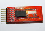
2. Buy a cheap mini-voltmeter, e.g. sold on eBay as 'Lipo Battery Voltage Indicator Checker' (usually $2-3).
Buy operational amplifier circuits, resistors... Build the current source, connect this on the voltmeter input ( it's possible to use a second operational amplifier to).

**broken link removed**

460964874_665.jpg


To measure resistance – connect the unknown resistor across current source probes. Some current flows through the resistor, from constant current source. Now according to Ohm’s law voltage is produced across it. This voltage is directly proportional to its resistance. This voltage is buffered by the buffer amplifier and then fed to A/D converter, to get digital display in Ohms.
 

Sky_123 I was thinking of a tiny tester for testing tiny ohms.. MOST DMM's are useless with 3.5 digits and 200Ω full scale.
Any cheap DMM will do the trick for > 1 Ω but if you want to find shorts.... maybe you don't.... what I said is best

I just found one that does what I said
**broken link removed**

If you want automated window comparator for any RLC value. Get an RLC meter like I have for $250.

It should be esy to substitute other op amps and transistors that are equiv. and run it off 3V or 9V

- - - Updated - - -

I see EXtech no longer makes the great RLC meter I have but this one at half the price does just R but does ratios so you can see if the tolerance is off after calibrating with an ideal part.
**broken link removed**

If looking for a better used one look for the the EXTECH 980123 RLC meter with auto ranging 10 decades and auto MIN MAX or set tolerance for bin sorting or GO-NOGO test
.
 

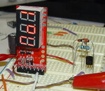
One of the tiny DIY solution. :grin:

I have already bought this cheap mini-voltmeter on eBay (for USD 1.5) so it was not so complicated for me to test in practice the proposed solution. For a quick test I have implemented the most simple current source, that’s one PNP transistor, two diodes and two resistors.
I have chosen for 1mA, so using a 9 volts power supply we get a maximum test range around 7.5 k, and the minimum range down to 0.10 k. There was only one minor problem, the 'lipol voltmeter' was designed to test all 6 inputs and to toggles between each cell than give total voltage of pack. In order to stop the additional measurements after a single cell, I have cut the PCB to get a direct connection to the power supply. In this way the first input is measured and then the total voltage is displayed. Unfortunately the circuit I have tested has an offset display error on the first input compared to the other inputs, so the total voltage displayed is lower than the first input value (~0.03). Who knows, maybe similar circuits available on the market are more accurate than the one I have tested. :roll:
 

Attachments

  • Voltm Lipol tester.png
    Voltm Lipol tester.png
    150.8 KB · Views: 142
  • a2.jpg
    a2.jpg
    211.1 KB · Views: 75
  • a3.jpg
    a3.jpg
    399.2 KB · Views: 84
  • a4.jpg
    a4.jpg
    398.5 KB · Views: 74

Looks like a great choice Mister_RF.
I would consider the LM317 as a 3 terminal precision current source and switch in different current shunts between pin 2 & 3, where I = 1.250V/R.. not sure what the min/max range is. Usually 0.01,0.1,1,10mA for each decade .
 

Status
Not open for further replies.

Part and Inventory Search

Welcome to EDABoard.com

Sponsor

Back
Top