Continue to Site

Welcome to EDAboard.com

Welcome to our site! EDAboard.com is an international Electronics Discussion Forum focused on EDA software, circuits, schematics, books, theory, papers, asic, pld, 8051, DSP, Network, RF, Analog Design, PCB, Service Manuals... and a whole lot more! To participate you need to register. Registration is free. Click here to register now.

Determining fuse rating for AC line

Status
Not open for further replies.

ZeroKool

Newbie level 4
Joined
May 5, 2012
Messages
7
Helped
0
Reputation
0
Reaction score
0
Trophy points
1,281
Activity points
1,376
Hello ALL,
I am trying to find calculations/formula for the AC line equivalent current if the load's power is known. I need to calcuate this so I can size up the ac line fuse or common mode choke size, Can anyone help me calcuate them or lead me to a good information source?

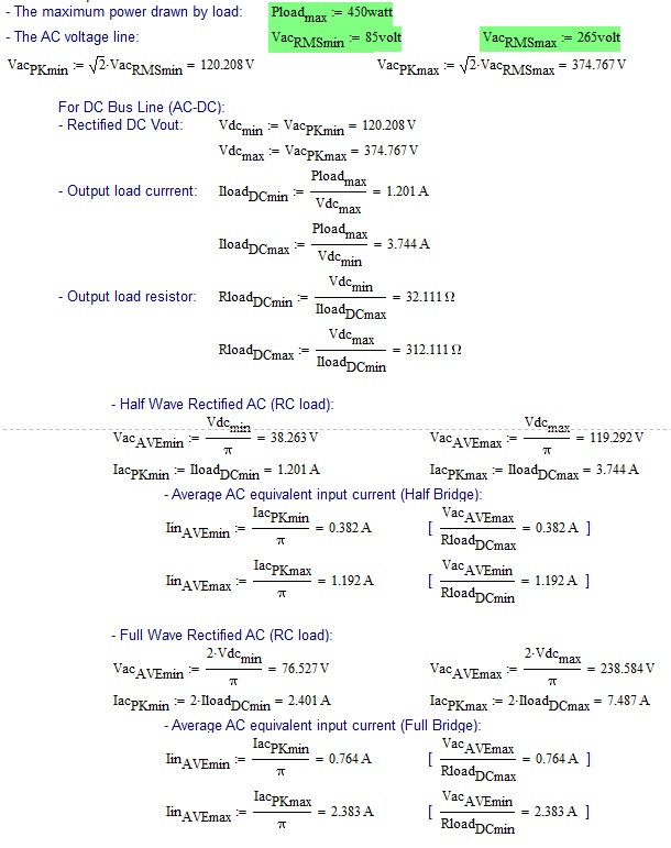
Lets say the power drawn by the load is 450W, what is the equivalent ac current for:
Rectified ac wave:
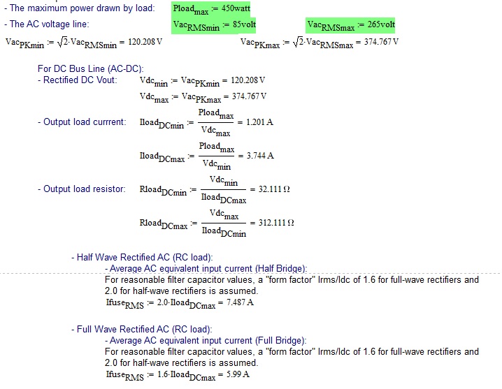
Half wave: what is the ac equivalent input current?
Full wave: what is the ac equivalent input current?
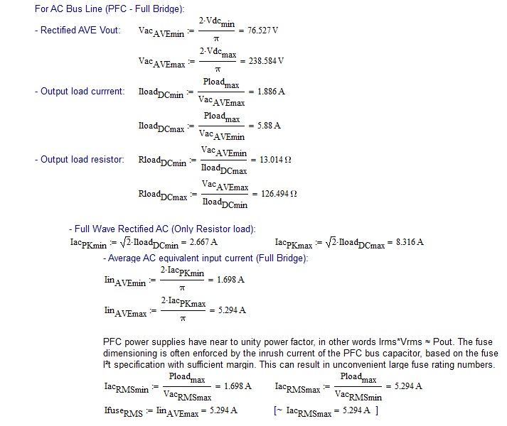
PFC:
what is the equivalent ac input current?

Thank you
 

Not sure its that simple, on half wave you get current pulses on alternate half cycles only. On both types the current waveform is very peaky, there being current only for a few 10s of degrees. A bigger problem is that on initial switch on, as the reservoir capacitor charges , there is a large inrush of current. This means that the fuse should be a "slow blow" (thermal lag) fuse and as fuses are only available in certain sizes the next size up from you calculated current. So 450 W @ 230 V = ~2A, use 3A slow blow.
Frank
 

Hi Frank
Thank you for your reply. Your answer (3A fuse) is only specific to 230V (450W), and I am assuming that it is for an RC filtered after the rectification. If the requirement changes, the 3A fuse couldn't be apply especially at higher power. There is also PFC (no RC filter) requirement, after the rectification, it is not DC? I don't think the fuse selection for the PFC is the same as the DC rectification, I might be wrong on this.

However since my initial post and your reply, I have worked out some calcuations and hope that someone can confirm that it is correct [attached with this post]. If it is correct I hope it help other people as well.

I am still in the process of calcuating the fuse for a PFC, assuming that it is not the same as the RC filtered rectification.


Attachments

  • DC_RC-Filtered.jpg
    DC_RC-Filtered.jpg
    134.3 KB · Views: 55

I don't see current waveforms considered in your calculation, in so far I don't expect that it's correct for conventional power supplies with filter capacitor. For reasonable filter capacitor values, a "form factor" Irms/Idc of 1.6 for full wave rectifiers and 2.0 for half wave rectifiers is assumed.

PFC power supplies have near to unity power factor, in other words Irms*Vrms ≈ Pout. The fuse dimensioning is often enforced by the inrush current of the PFC bus capacitor, based on the fuse I²t specification with sufficient margin. This can result in unconvenient large fuse rating numbers. Manufacturers sometimes loves to add unreasonable margins on their own, ending up in something like a 3.15 A slow blow fuse for 3W(!) 90 to 260 V input SMPS.

A serious inrush current calculation resulted in a fuse value of 0.16 A, still a multiple of the value according to the real input power.
 
FvM,
Thank you for your reply. Your explanations are reasonable. I will repost the calculations for you or anyone else to confirm that it is correct.


PFC: Calculation assumed inrush current is controlled (negligible)


Thanks
 

Yes, that's basically what I suggested. In the PFC case, a surcharge for losses should be added. In the capacitive filter case, the form factor depends also on capacitor values and circuit series impedances. The said numbers are only a rough estimation.
 

Status
Not open for further replies.

Similar threads

Part and Inventory Search

Welcome to EDABoard.com

Sponsor

Back
Top