Continue to Site

Welcome to EDAboard.com

Welcome to our site! EDAboard.com is an international Electronics Discussion Forum focused on EDA software, circuits, schematics, books, theory, papers, asic, pld, 8051, DSP, Network, RF, Analog Design, PCB, Service Manuals... and a whole lot more! To participate you need to register. Registration is free. Click here to register now.

Driving LED using a MOSFET and a Microcontroller

Status
Not open for further replies.

syedaban

Newbie level 6
Joined
May 27, 2012
Messages
11
Helped
0
Reputation
0
Reaction score
0
Trophy points
1,281
Activity points
1,347
Hi,
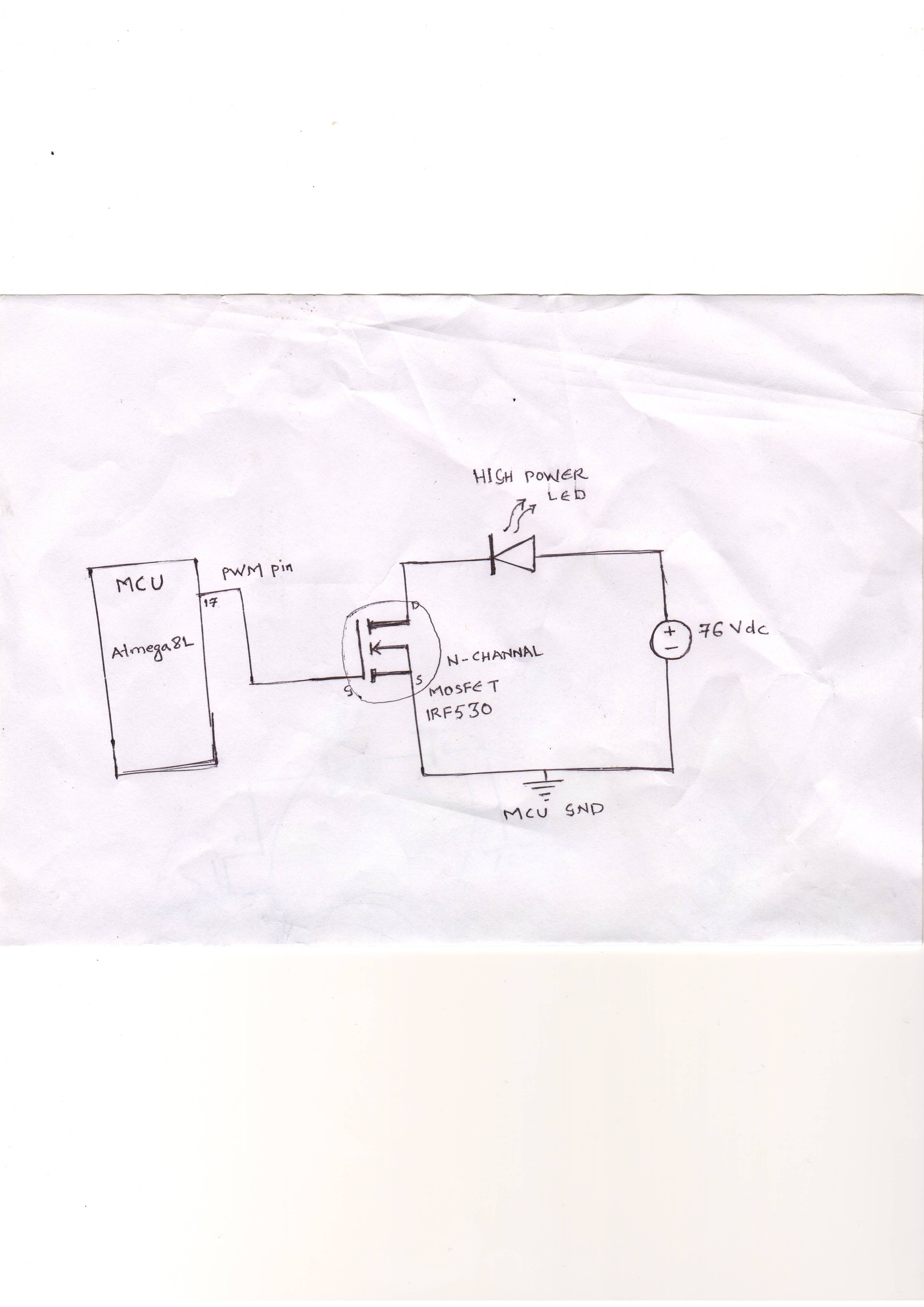
We are trying to drive a 70V LED using a microcontroller and a n-channel MOSFET.
The problem is that we are getting spikes on the microcontroller if we have a common
ground for gate and the supply.

I want isolation for the mcu from the LED.please help...

Regards,
Syed Aban


    V

    Points: 2
    Helpful Answer Positive Rating
I think it is a good idea to use an optically coupled MOSFET driver. In that way, you have isolation as well as the driver section on one chip.

Two such drivers are TLP250 and HCPL3120. They are also relatively common and easy to use. So, you can try them.

www.avagotech.com/docs/AV02-0161EN
www.datasheetcatalog.org/datasheet/toshiba/2109.pdf

However, with good filtering and bypassing, you can use the same ground and avoid the additional driver. Maybe you haven't decoupled and/or filtered enough/properly.

Hope this helps.
Tahmid.
 

    V

    Points: 2
    Helpful Answer Positive Rating
Thanks a lot for your reply.
Can you please suggest me a circuit that will filter the noise and also provide
isolation for MCU with or without the MOSFET driver.

Regards,
Syed Aban
 

A start would be decoupling and filter capacitors across all power lines - all VDD and VSS lines of microcontroller, drivers and across all power supply lines. You may also use a filter choke in series.

For isolation, use 2 different power supplies - one for the microcontroller, one for the MOSFET. Interface the microcontroller and the MOSFET with an optically-coupled driver.
 

I am using only a single power supply as having different power supplies would make the circuit bulky
 

If you're using a 50Hz transformer, then you can derive two power supplies from the same transformer.

But if you do have only one power supply with both parts of the circuit having the same ground, then you can't really have isolation between the two stages.

A schematic would help.
 

Hi,
Check the link below,for the basic diagram. DC source is from the SMPS unit.


I know this is an old problem, but I think the issue is radiated (ingress) noise not conducted (ingress) noise on a common ground.
A ground shift from lossy ground wires would create a DC shift not a spike from the I^2R losses in the common ground wire to power source .

So in this case you want to use a snubber diode to prevent long wire inductance and/or capacitive coupling ingress reduced with shielding or a ferrite bead on the gate drive and common mode ferrite choke to the switched load and ground. It may need any or all of the 3 suggestions depending on layout.
 

Hi,
Please suggest a schematic to overcome the noise.
Thanks in advance..
 

In my view you need to refer this document bcz any mosfet driver circuit had it's own constants like frequency of operation, turn-on time intervals , capacitance etc.

**broken link removed**

Good luck
 

Status
Not open for further replies.

Part and Inventory Search

Welcome to EDABoard.com

Sponsor

Back
Top