ste2006
Advanced Member level 4
Hi Guys,
I have been struggling with this issue for a while and cant seem to find a definitive reliable solution to what would seem like a common problem.
I basically have a GSM module that will operate between 3.4 - 3.8V. I also have a Li-ION charger IC that will charge up a 3.7V 1000 mAh Li-ION Battery for me.
Question is how do i connect both a DC fixed 3.7V supply and the battery supply to the system at the same time to if the main power source fails the battery will back it up and once normal power comes back it will switch back to this.
It generally seems not to be recommended to just place the load accross the battery being charged as if enough of a load is being drawn the battery management IC may never think it is charged??
I have built circuits using FETs, diodes etc but all give me a voltage drop which then brings my battery voltage down too low.
Peak current in bursts will be up to 2Amps so that also poses its own issues from the charger side. DC voltage starts at 5V and was just going through a regulator to step it down.
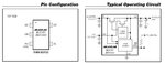
Maxim are showing on one of their IC's the load connected straight accross the battery (as attached) but Microchip then recommend not to do this!!
Anyone any thoughts???
Thanks,
Stephen
I have been struggling with this issue for a while and cant seem to find a definitive reliable solution to what would seem like a common problem.
I basically have a GSM module that will operate between 3.4 - 3.8V. I also have a Li-ION charger IC that will charge up a 3.7V 1000 mAh Li-ION Battery for me.
Question is how do i connect both a DC fixed 3.7V supply and the battery supply to the system at the same time to if the main power source fails the battery will back it up and once normal power comes back it will switch back to this.
It generally seems not to be recommended to just place the load accross the battery being charged as if enough of a load is being drawn the battery management IC may never think it is charged??
I have built circuits using FETs, diodes etc but all give me a voltage drop which then brings my battery voltage down too low.
Peak current in bursts will be up to 2Amps so that also poses its own issues from the charger side. DC voltage starts at 5V and was just going through a regulator to step it down.
Maxim are showing on one of their IC's the load connected straight accross the battery (as attached) but Microchip then recommend not to do this!!
Anyone any thoughts???
Thanks,
Stephen