Continue to Site

Welcome to EDAboard.com

Welcome to our site! EDAboard.com is an international Electronics Discussion Forum focused on EDA software, circuits, schematics, books, theory, papers, asic, pld, 8051, DSP, Network, RF, Analog Design, PCB, Service Manuals... and a whole lot more! To participate you need to register. Registration is free. Click here to register now.

pic 16f877a batterycircuit connection life monitor.

Status
Not open for further replies.

hezbon

Newbie level 4
Joined
Mar 15, 2012
Messages
6
Helped
0
Reputation
0
Reaction score
0
Trophy points
1,281
Activity points
1,335
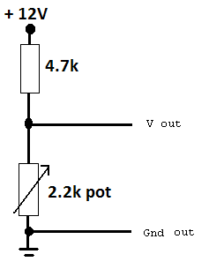
am working on a project to monitor a battery life using pic 16f877a. i want to monitor the voltage of the battery from port a pin 0, the battery i want to monitor supplies 24v so i want to exactly monitor the battery but my fear is that the voltage is too high for the pic and i think it can spoil the pic. anybody with an insight into the connection or sample circuit to help
 

If you use PIC16F877A, you'll have to scale the voltage down to within the PIC's limit. You can do that with a simple voltage divider employing 2 resistors.

Hope this helps.
Tahmid.
 
  • Like
Reactions: hezbon

    hezbon

    Points: 2
    Helpful Answer Positive Rating
Tahmid thanks. that is what I had thought of. I have the circuit designed and calculations, but there is only one problem when am simulating with ISIS am using 12V supply battery and dividing down into four using four resistors. that i mean the first two resistors would give 6V and again using the divider on this voltage am expecting 3V as an ideal value, but the value in the ISIS is around 2.3V, that narrows to voltage loss across the resistors thought, so my worry is in my logic in C code am taking that voltage from my port, and multiplying it by a factor of 4 to get back to 12V to display on the screen via rs232 but my calculation would give 9.2V. This leaves a big difference but am trying to add that difference value into my code, but my worry is as the voltage reduces if i connect this battery to a motor the value that i will be adding would change and I think it would affect my data so much in real circuit implementation because i gaze ISIS should be giving the 3V. any insight into circuit design or algorithm would be great help thank you. dont tackle transmission through rs232 with that am ok
 

You shouldn't have too large a voltage loss in the resistors. That would be a problem.

What are the values of the resistors you are using? And how are they connected? The loss would change depending on the voltage.

You can use this:
26_1339048394.png


Adjust the pot until you have 3V at the output with 12V input. Then there shouldn't be a problem. You can use fixed resistors as well, but using a pot allows you to "tune" the voltage, allowing for tolerances in the resistance of the fixed resistors.

Hope this helps.
Tahmid.
 
  • Like
Reactions: hezbon

    hezbon

    Points: 2
    Helpful Answer Positive Rating
ok Tahmid I can see your idea right there. Let me connect and simulate, but is there in Proteus ISIS away i can get a variable resistor that can change value at runtime of simulation? like the lm35 so that i can vary the voltage drop at different levels and see what am logging into my database
 

Use the part "POT-HG". You can use that for simulation. You can alter the resistance while simulation is running.

Hope this helps.
Tahmid.
 
  • Like
Reactions: hezbon

    hezbon

    Points: 2
    Helpful Answer Positive Rating
The circuit functioned correctly, except I now want to build this circuit to dynamic to be able to apply it over a given voltage range, and also include ac voltage in it, so that it can measure ac voltages upto 240v. I have tried to figure out to use a comparator so that I have an output of 5v from comparator but my concern comes at a point on my understanding that comparator would only output when the voltage is equal or greater than the reference voltage, so I will probably only have 0 or 5v so cannot compare the varying voltage of the source.
Is there away I can design my circuit to respond to different sources? in the meantime let me try to come up with logic as I wait for your insights thank you.
 

Status
Not open for further replies.

Part and Inventory Search

Welcome to EDABoard.com

Sponsor

Back
Top