baby_1
Advanced Member level 1
Hello
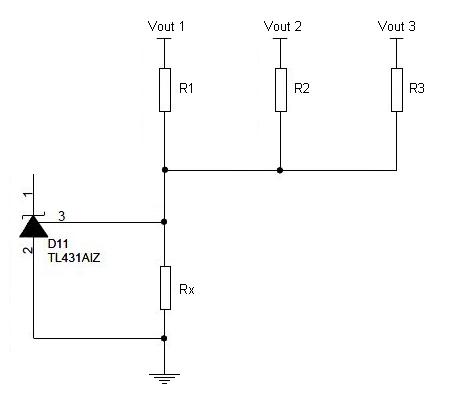
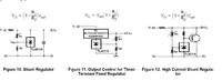
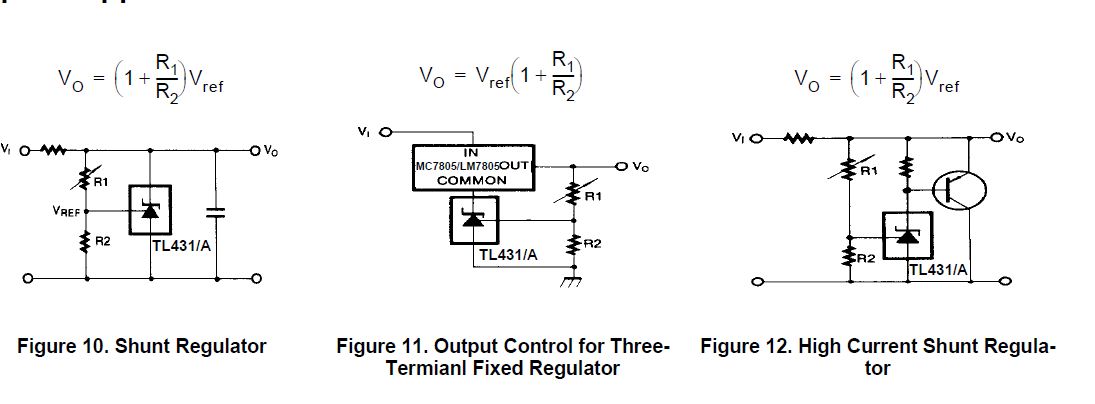
as you see this image,vout is equal :
)
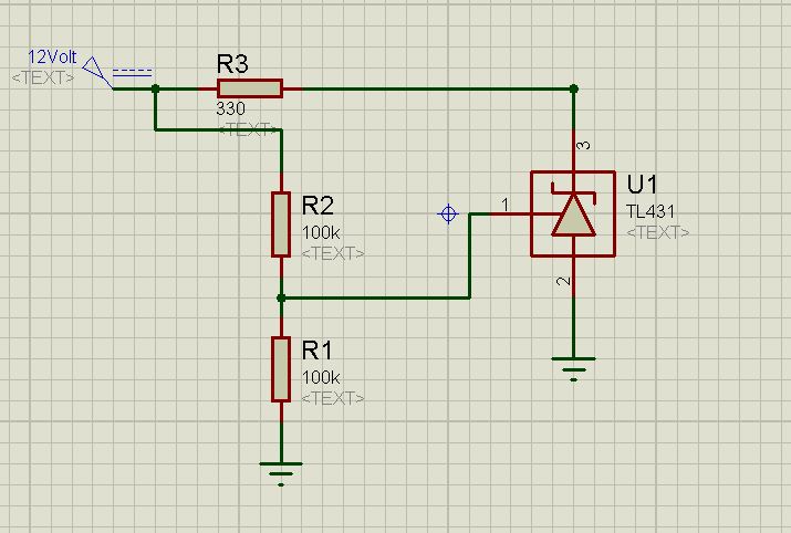
but in SMPS circuit i see something interesting.
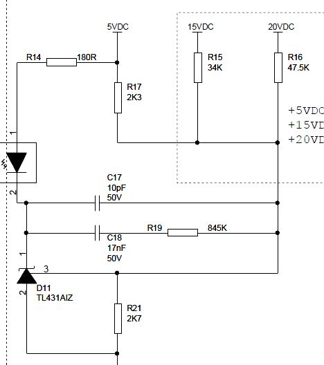
Vout=2.5(1+47.5/2.7)=46.48 :shock:
another one
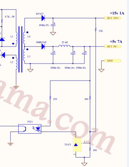
Vout=2.5(1+12000/100)=302.5:shock:
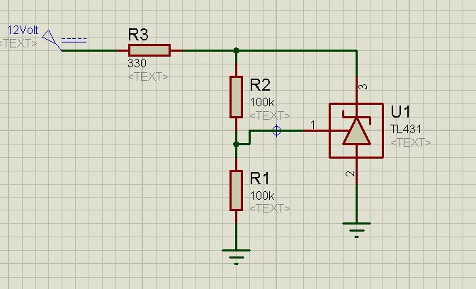
if i change the R1 and R2 in this equation i have these result
Vout=2.5(1+2.7/47.5)=2.64
Vout=2.5(1+100/1200)=2.708
it means if output voltage is fix on the desire volt it has error !!!!
why?
what is my fault?
---------- Post added at 21:20 ---------- Previous post was at 21:09 ----------
Please tell me how the Tl431 work in SMPS circuit?
as you see this image,vout is equal :
but in SMPS circuit i see something interesting.
Vout=2.5(1+47.5/2.7)=46.48 :shock:
another one
Vout=2.5(1+12000/100)=302.5:shock:
if i change the R1 and R2 in this equation i have these result
Vout=2.5(1+2.7/47.5)=2.64
Vout=2.5(1+100/1200)=2.708
it means if output voltage is fix on the desire volt it has error !!!!
why?
what is my fault?
---------- Post added at 21:20 ---------- Previous post was at 21:09 ----------
Please tell me how the Tl431 work in SMPS circuit?