Fragrance
Advanced Member level 4
- Joined
- Jul 26, 2002
- Messages
- 1,190
- Helped
- 248
- Reputation
- 496
- Reaction score
- 202
- Trophy points
- 1,343
- Location
- East Of Earth
- Activity points
- 8,933
Follow along with the video below to see how to install our site as a web app on your home screen.
Note: This feature may not be available in some browsers.


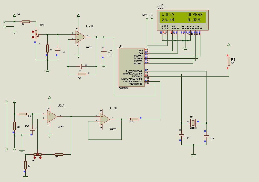
I see this request a lot for voltmeter/ammeter so I thought I'd share my design that I'm working on at the moment using a VREF of 4.096V
The volatge side works really well as you can see from the readings of the vout compared to the LCD, This works really well on my dev board,max voltage 50V max current 12.34amps at the moment.
The current part I'm still working on as this part really is down to the set up required really. I like to use an op-amp set as a gain amp get better readings I find. I've got to test the current part on my dev board once I get this side set up on it then I know where I'm going.
Notice I've used fixed value resistors(.1%) as the calibration is done in software more accurate I think.
Once I know it's complete I need to layout the PCB for it, I intend to use it im my PSU 0-30V 0-5A
View attachment 85980
View attachment 85981
@fragrance the current sense resistor, is it meant to be at the high side or low side. thanks
Fragrance
I don't mean to offend you in anyway and these are my thoughts on your meter
Looking at your schematic, The voltage side I've never seen a setup like that before and confused how it works, I ran the sim and with the input volatage set to 25V and pot set to 50% you get 4.23 on the wiper with an ouput voltage of the op-amp 4.02V and with a reading of 48.14 on LCD but after that it gets saturated with the pot set between 51-100% you get 11.35V on wiper with the ouput of the op-amp still showing 4.02V and display remains the same 48.20V between 51-100%. I think using a 1K pull down and 1k on the input resistor is bad practice working out the maths you would get 12.5v on the wiper. The current side normally would use both 1k resistors feeding into the op-amp with a 43k resistor acrross pin 2 and pin (43K would increase the gain but this would need to be worked out depending on the gain/ouput voltage on the max current reading you need) I can see that the B part is acting as a buffer for it.
I've attached my meter file for you to have a look/play with for the way I do it feel free to post your comments about it.
When you first start the sim you will see the input voltage is set to 10.47 and the display reads 10.31 this is only the fact I was testing the calibration part once set it stores it in the eeprom (but ISIS does not store it.)
The way to calibrate is
Step 1
before starting the sim click the the up/down arrow on the ENT button(to hold it down to enter calibration) then start sim, this will show you that your in calibration mode until you release the button then you calibrate the voltage using the up/down then once it reads the same press enter
Step 2
once you pressed enter after the voltage calibration you calibrate the amps the same way then press enter this will automaticlly restarts the meter and you will display the voltage/amps to what ever it as been calibrated to, but once you stop and restart sim it will go back to the default (not in real time though only in isis)
Voltage side is working correctly but the amps side is just the value of R7 may need to be changed depending on the V drop accross a 0.1R resistor or what ever way you have set up to measure current, For testing use RV2 with a max voltage input of 100mV. as for the Vref anything can be used aslong it is 4.096V vref (just noticed R2 value is way to high but the LM4040 does not have a sim model so I set it manually to 4.096V R2 I used a 150R resistor in real time wiht the LM4040
Sorry don't mean to highjack your thread
wizpic
") didnt read good enough
didnt read good enough