Continue to Site

Welcome to EDAboard.com

Welcome to our site! EDAboard.com is an international Electronics Discussion Forum focused on EDA software, circuits, schematics, books, theory, papers, asic, pld, 8051, DSP, Network, RF, Analog Design, PCB, Service Manuals... and a whole lot more! To participate you need to register. Registration is free. Click here to register now.

[SOLVED] 555 Flashing LED - Help Needed

Status
Not open for further replies.

Gr3x

Junior Member level 1
Joined
May 24, 2012
Messages
17
Helped
0
Reputation
0
Reaction score
0
Trophy points
1,281
Location
Ontario
Activity points
1,401
Whats up guys,

So I hooked up an LED with a 555 timer and am trying to get the LED flashing.

https://www.555-timer-circuits.com/flashing-led.html

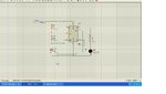
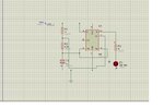
I built the circuit based off the schematic shown in the link above, but my LED will turn on and remain on. I'm using 9v power supply and a 47 micro-farad capacitor instead of the 1micro-farad cap he recommends using. If anyone has any idea as to why this is happening hit me back.

Heres a picture of my circuit

555led.jpg
 

That looks like a Tantalum capacitor. Are you sure it's connected the right way around?
 

Switching the caps polarity doesn't change anything. The tantalum is "104".
 

You yourself pointed out the source of the problem without knowing it. R1, R2 and C1 together determine the flashing rate (frequency). If you had used the values given on the schematic, the flashing rate would be about 1.5Hz, that is, three flashes every two seconds.

By increasing the capacitor value 47 times, you also increased the time constant 47 times. The flashing frequency is reduced 47 times to roughly once every 30 seconds. That probably made you think that the LED remained lit up permanently. The solution is obvious: Change the capacitor value to 1uF or thereabouts. Lower values will give you a faster flash rate and higher values will make it flash more slowly.
 

The frerquency of oscillation is dependent on the Capacitor. I dont understand what made you to put 47uF against as suggested.
Refer 555 data sheet and you get to know more about the importance of each components in the circuit.
 

The tantalum is "104".
"104" probably indicates a value of 100nF (as opposed to 47uF), in which case it's flashing too fast for you to see.
 
Last edited:

decrease the frequency by varyin the cap value and u can see the led flashing.
as frequency is inversily proportion t cap in the equation, including another cap in parallel to this cap wud do the work ...tell me if u try dis config.

---------- Post added at 11:15 ---------- Previous post was at 11:14 ----------

decrease the frequency by varyin the cap value and u can see the led flashing.
as frequency is inversily proportion t cap in the equation, including another cap in parallel to this cap wud do the work ...tell me if u try dis config.
 

I found a 1mF electrolytic cap and switched it in. When I apply power the light doesnt turn on. I tried switching resistance but still nothing.

Also when I remove the ground lead from Pin 1, the light comes on and stays on. Does this mean anything?
 
Last edited:

its working may be you have hardware connection problem see the result
 

Attachments

  • led2.JPG
    led2.JPG
    138.4 KB · Views: 77
  • led1.JPG
    led1.JPG
    89.3 KB · Views: 83

check out whether led is workin or no. n nextly if led is workin fine try with slightly lower value of cap or add sm more resistance to the path...
for led t flas u jst need to increase time period so dat the switchin s visible t u...
 

I found a 1mF electrolytic cap and switched it in. When I apply power the light doesnt turn on.
Then either your wiring is wrong or one of the components is defective. Check your wiring very carefully.

I tried switching resistance but still nothing.

Also when I remove the ground lead from Pin 1, the light comes on and stays on. Does this mean anything?
Unless you have a good theoretical knowledge and practical experience, don't change the original design. The design should work. Changing it without knowing what you're doing will only mess things up even more and you may damage the components. You may have already done so.
 

Ok thanks for the tip... I switched added in a new 555, a new 1mF cap, new LED an still the light isn't turning on.
 

post your updated change circuit pics and if possible draw your connection on paper which not in schematic but which you actually connected on your breadboard
 

AtpAwBQCIAIVcL3.jpg

The current circuit I'm using
 

pin 4 and pin 8 don't look short
 
  • Like
Reactions: Gr3x

    Gr3x

    Points: 2
    Helpful Answer Positive Rating
Oh haha, had to rebuild the circuit quick so must of F'd it up. Circuits working good now finally. Thanks alot for the help men
 

Calculating Frequency Of Blinking LED

So I have a completed 555 circuit with an LED blinking at 2.5Hz (I believe) with a 1 micro farad capacitor, 1 470k resistor and a 1k resistor. My question is: How would I go about calculating which caps or resistors to use to control the frequency at which the LED will be blinking. For Example, making the LED blink every 30 seconds, every 15 seconds etc...


Don't create new thread for a question related to the same circuit.
Threads merged. [alexan_e]
 

Status
Not open for further replies.

Similar threads

Part and Inventory Search

Welcome to EDABoard.com

Sponsor

Back
Top