Continue to Site

Welcome to EDAboard.com

Welcome to our site! EDAboard.com is an international Electronics Discussion Forum focused on EDA software, circuits, schematics, books, theory, papers, asic, pld, 8051, DSP, Network, RF, Analog Design, PCB, Service Manuals... and a whole lot more! To participate you need to register. Registration is free. Click here to register now.

what I have to do to know the gain of an opamp (for beginner) in CADENCE

Status
Not open for further replies.

Fred556

Junior Member level 1
Joined
May 23, 2012
Messages
16
Helped
0
Reputation
0
Reaction score
0
Trophy points
1,281
Location
Portugal
Activity points
1,393
Hi,

could somone help me?

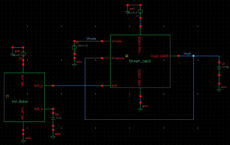
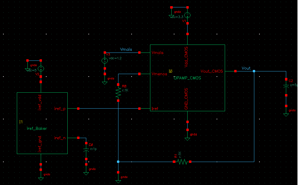
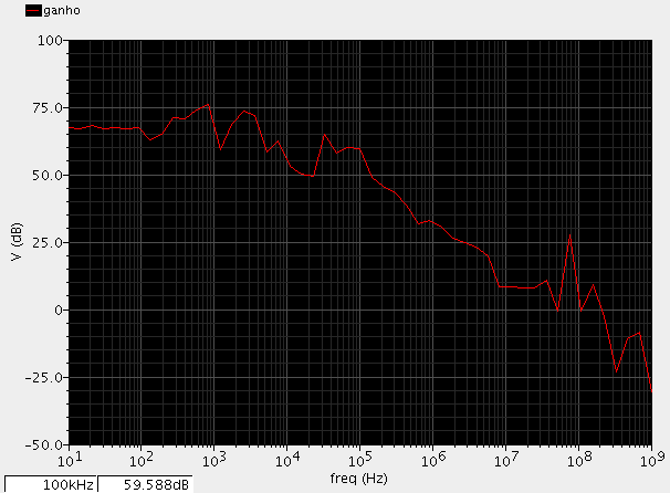
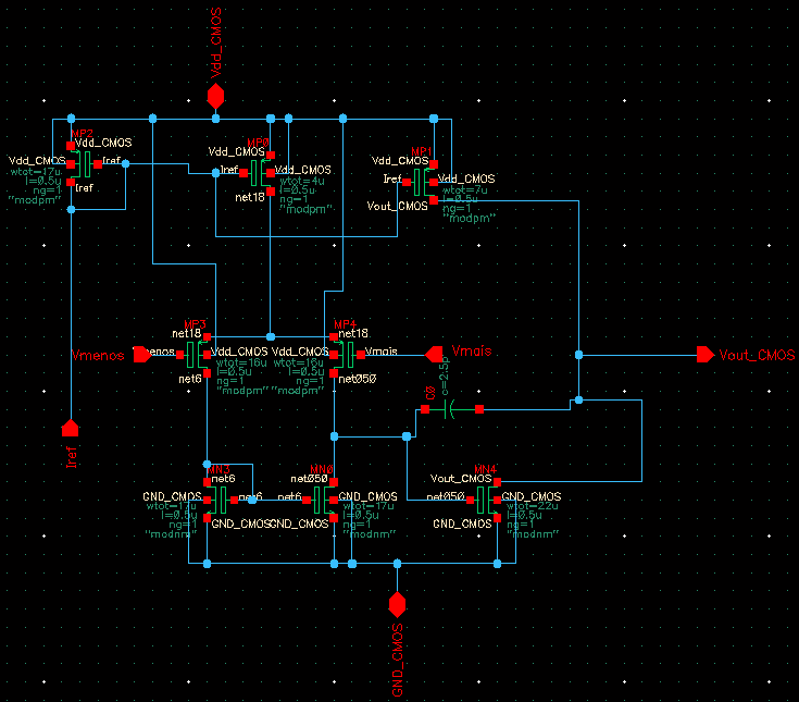
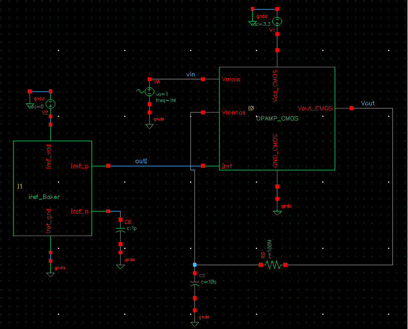
I've made my opamp and I would like to know the gain, phase margin, etc..

But I don't know how to do that.. Could someone give me the step to do it? I have cadence 6 (i think). What i find on the internet it's:
Results-->Direct plot--> AC magnitude & phase but I don't have this on my cadence..

Could someone give me a link or something?
Thanks in advance.
 

Re: See this CADENCE tutorial, sl. 14 & 15 :

See this C@DENCE tutorial, sl. 14 & 15 : View attachment 74754

In my ampop I don't have "outp" and "outn", I only have one ouput and not 3 like the one in the tutorial... Could you help?

I want to calculate the gain, and th tutorial does: "value(db20(VF(“/outp”) –VF(“/outn”)) 0)" but if I had only one output how can I do?


this is my opamp:
 
Last edited:

Re: See this CADENCE tutorial, sl. 14 & 15 :

I want to calculate the gain

In your circuit, gain=1 , due to full negative feedback.
If you want to measure gain & phase vs. frequency, use your opAmp in open loop configuration.
There are a lot of threads about this in the forum. E.g. search for "Middlebrook" .
 
Re: See this CADENCE tutorial, sl. 14 & 15 :

If I do an opamp with a negative feedback, what i have to write on the ouput in cadence?
"value(db20(VF("/Vout")/(VF(“/Vmais”) –VF(“/Vmenos”))))" ?


thanks a lot for helping me because I'm desperate...

---------- Post added at 18:27 ---------- Previous post was at 18:24 ----------


Re: See this CADENCE tutorial, sl. 14 & 15 :

I'm desperate...

So why don't you follow my suggestion? Here's a good thread to learn from:

0. Make sure your circuit works well in DC (correct operation point?)
1. Use a DC-only negative feedback (large L , large C)
2. Insert a unit (1V) AC source in series with your (hopefully correct) DC bias at the non-inverting input (Vmais)
3. Probe your output
4. Run an AC analysis
5. Plot 20dB(Vout) and phase(Vout)
 
Hi,

could you tell me how I can put an AC source?
DC source is in analogLib (vdc) but I can't find an AC source... There is another name for an AC source? I was looking for vac but doesn't exist.

Thanks.
 

Hi,

could you tell me how I can put an AC source?
DC source is in analogLib (vdc) but I can't find an AC source... There is another name for an AC source? I was looking for vac but doesn't exist.

Thanks.

Look for VSIN
 
In analog lib ,you will see "Vsin" ,put it in series with the input voltage source V3 at vmais;
Vmenos=1.2V DC only,remove the feedback loop.
For Sinusoidal source ,take Amplitude=Magnitude=10mV,Freq=according to your application(e.g. 1M).
Now do AC analysis,sweep frequency from 1 to 1GHz in log scale with 100 points per decade for good resolution of graph.Go to Output--> to be plotted: select on schematic vmais ,vmenos and vout on the schematic window.(Select the nets not the nods).Netlist and run.

Now you have AC analysis window.Go to calculator,Select wave,First select vmais,then select vmanos,then press minus(-) sign,press eval.
Now select vout and Vmais-vmanos on the graph,and press divide(/) sign on calculator,Click eval.see the gain at freq=1Hz.this is DC gain.
Now select the vout/vmais-vmanos and press db20 and eval.you will get the db curve.
Now select the vout/vmais-vmanos again and press phase and eval.
simiarly u can find phase margin,gain margin,gain bandwidth product,3 db freq.........and so on
Keep it in mind that Calculator in cadence takes the expression like this:
Operand1,operand2,operator
 
could someone give me a tip why does my opamp gain is like this?


it shouldn't have this "zigzag". Anyone know's the problem?

I'm a beginner so I have no idea.. Thanks in advance.
 

my opamp schematic:


and my bench schematic(from the book, baker 3ª edition chapter 24):


thanks for helping me.
 

Status
Not open for further replies.

Part and Inventory Search

Welcome to EDABoard.com

Sponsor

Back
Top