Continue to Site

Welcome to EDAboard.com

Welcome to our site! EDAboard.com is an international Electronics Discussion Forum focused on EDA software, circuits, schematics, books, theory, papers, asic, pld, 8051, DSP, Network, RF, Analog Design, PCB, Service Manuals... and a whole lot more! To participate you need to register. Registration is free. Click here to register now.

Alternative to 16f628a for interrupts

Status
Not open for further replies.

vaka85

Advanced Member level 4
Joined
May 9, 2008
Messages
100
Helped
0
Reputation
0
Reaction score
0
Trophy points
1,296
Activity points
2,112
Hi all,

I've done a project with pic16f628a, it is very simple, since I'm a beginner in programming...
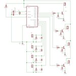
It takes 4 piezo buzzers as inputs, and when they provide a pulse, a led turns on at the corresponding output.
The problem is that everything is without interrupts, so there are some problem with the polling:
if the input pulse are fast (for example 2 o 3 per second), and almost at the same time between the inputs, a lot of pulses are "lost". The biggest problem occures when there are 2 very close pulses between two different inputs; in this case one of the two outputs almost always doesn't turn on.

That's why I'd like to use interrupts. But looking at the 628 datasheet it seems that there is only one input available for interrupts.
So, here is the question, could you tell me a good (and cheap) alternative to the 628?
I need at least 4 inputs(everyone usable with interrupts), but the more the better!

Thank you
 

Hi,

In addition to Alertlinks - What oscillator are you using.

You are saying your buzzer operates at a 'fast' 2 or 3 times per second, the 628A using its internal 4 mhz oscillator can execute 1 million instructions per second, so no need to looks for another 'faster' chip.


To poll 4 i/o pins would take say 50 instructions, so what is happening with your code ? Post your code so we can see whats happening and help more.
A diagram would be interesting to see how your buzzers are operated / connected.
 

Thank you for your answers..

By looking at ALERTLINKS links it seems that the 628 accepts the external interrupts an all the RBx pins, and this would be good... I don't know why somewhere else it's written that 628 accepts only one external interrupts.. It's a little bit confusing to me.

However, here are the schematic (attached) and the code. It's written with mikroC because I don't know assembler..

Code:
void main(void) {
    CMCON = 0x07; // switch off comparators; 

     TRISA = 0xFF;     // set portA as inputs
    // set portB as outputs
    TRISB = 0;
    PORTB = 0; //init portb, all leds off at start

while(1)   // continually
  {
       if (PORTA.f0)      // if there's a trigger pulse
       {
          PORTB.f0 = 1;     // turn the LED on
          Delay_ms(70) ;
          PORTB.f0 = 0;   // turn led off
       }
       if (PORTA.f1)      // if there's a trigger pulse
       {
          PORTB.f1 = 1;     // turn the LED on
          Delay_ms(70) ;         // wait 500 ms
          PORTB.f1 = 0;   // turn led off
       }
       if (PORTA.f2)     
       {
          PORTB.f2 = 1;     
          Delay_ms(70) ;       
          PORTB.f2 = 0;   
       }
       if (PORTA.f3)      
       {
          PORTB.f3 = 1;    
          Delay_ms(70) ;       
          PORTB.f3 = 0;   
       }

   }
}

It's very basic, but there are the problem that I described above..

The oscillator is an external 4 MHz crystal oscillator.
The buzzer are connected to a drum, so the input pulse speed depends on how fast the drummer plays, but it's tipically 2 or 3 times per seconds, and often there are 2 different inputs hit at the same time..
I thought that 4 MHz would be enough even if I use polling, but it doesn't work very well..

Thank you
 

Attachments

  • schema.jpg
    schema.jpg
    78 KB · Views: 152

You could be missing some pulses because your application uses a "while" loop to check for input. If you want to reliably detect input when it happens, you need to use an input-capture module or something that is interrupt-based.

By using your while() loop method, you can only detect a tap when the processor is not doing something else. Yes, your 4MHz processor is probably fast enough for straight polling, but not if you're littering 70ms delays throughout your routines.
 

Hi,

Think you need to sit down and do a simple flow chart of the logic you need.
As Milesguiden says delays are the last thing you need.

Try something along these lines, polling and recording the hits at 4meg would result it the inputs being checked probably a 1000 times a second

Is Sw1 on
Yes, set a Sw1Flag On, goto Check Sw2
No
Was SW1Flag On
Yes, record a Hit, Clear SW1Flag, goto Check Sw2
No

Check Sw2 etc
 

Using the interrupt on change feature of PORTB would be the most sensitive in terms of time but if you are just waiting for a signal it's just as quick to read the whole port, store the value, read it again and XOR the saved and new values. If any pin changes state, the XOR'ed result will have a '1' in it at the bit that changed. Something like this:
Code:
while(1)
{
Temp = PORTA;
if(Temp ^ PORTA) DoSomething();
}

The DoSomething() will be called if any bit in PORTA changes.

Brian.
 

Thank you all.
So, as you said, the main problem in my software is not the polling, but the delays...

@milesguidon: I'd like to use interrupts, but looking again at the document that alertlink provided, it's written "This allows PIC16CXXX devices to support multiple external interrupts", but I have 16F and not 16C. This means that if I want to use multiple interrupts I have to change all the schematic and also the device.. Right?
Also, the delay is necessary to see the led turning on. If I don't use the delay command, how can I turn on the led and make it visible? Maybe with a capacitor, I don't know..

@wp100: even if I could make a flow chart (I've only basic programation knowledge), the problem of delay remains. Or am I wrong?

@betwixt: I don't see exactly what you are saying... what's the difference between my code and your one? Ok, apart from the XOR...

Ok, I know that I can do all of this by using multiple ne555 :) but I'd like to use pic so I can learn something...

Thank you for your help
 

Do not give up! If you only have one interrupt port, but 4 sensors, you *may* be able to hook each sensor up directly to a digital I/O port on the PIC like you are currently doing, but then connect a signaling diode with a small forward voltage drop between that I/O port and the INT pin on the PIC. I just thought of this...I'm not really sure if it's a great implementation, but it gives you the ability to jam 4 signals into one interrupt port, without those 4 signals affecting the original I/O ports that they are individually connected to. I think.

Since you're already using port RB0 (which is also the INT pin on your microcontroller), you'll have to shuffle your circuit around to free up that interrupt pin. **If the original output signal from your piezo buzzers is large enough**, then there should still be a good signal after the diode to trigger the interrupt port.

Then, in the interrupt routine, you can check which of the ports is logic HIGH. You can still use delays in your while() loop, because the interrupt routine ignores delays--the microcontroller slips out of the while() loop immediately, to service the interrupts (well, depending on priority and what other interrupts you have, but in this case you will just have the one hardware interrupt I'm assuming). If you're in the middle of lighting an LED, and your system gets a tap, the decision will be made immediately as to which sensor picked up the tap. Or, instead of using any delays at all (which uses processing power and increases current consumption), you can set up timers and make the whole thing interrupt-based, where you use internal timers to trigger the changing of the LEDs.
 
  • Like
Reactions: vaka85

    vaka85

    Points: 2
    Helpful Answer Positive Rating
@betwixt: ok.. If I understood, in the code that you posted, in the "doSomething" part, I have to do again a check to see which port has changed... So we are back to the delay part :)

@milesguidon: I'm not lying, that is exactly what I thought :) But I had some doubt about the signal amplitude from the buzzer, if it goes to two inputs... In these days I'll think about this solution, both the hardware and software part... Then I'll let you know, thank you very much!!
 

You could also get yourself a quad comparator and connect the 4 signals still to the I/O ports, but also jam one into the comparator, used in a simple rail-to-rail setup. You only need a quad comparator and a few resistors--what the comparator does is takes an input signal that goes past a threshold of your choosing, and stretches it out between the supply rails--so your 1.5V sinusoid pulse coming from the piezo unit is then a 0 to 3.3V (or whatever Vcc is) square wave--set your threshold at a few hundred mV to be sure it triggers correctly.

And then connect all comparator outputs through a diode (or maybe not) and then to the interrupt pin.
 

thanks for the advice milesguidon, you're very kind.
I'll think also to this solution, as soon as I have some free time... I'll be back to you soon ;)
 

you can also use a timer interrupt, that is executed every 1mSec. in it have counter variables for each LED, start the counter to 70 when you are turning a LED on, and turn the LED off when it counter reach zero. in this way you can remove the delays
 

yuvko, you can show me a short example of your idea? I don't understand it very well...

I was thinking about a solution that allows to mantain the same schematic, no changes..
What about something like this?
Code:
while(1)   
  {
       if (PORTA.f0)      // if there's a trigger pulse
       {
          INTERRUPT
          flag0=1
       }
       if (PORTA.f1)      
       {
          INTERRUPT
          flag1=1
       }
       if (PORTA.f2)     
       {
          INTERRUPT
          flag2=1
       }

   }


interrupt routine()
if (flag0)
   turn led0 on;
   delay;
   turn led0 off;
   flag0=0;
else if (flag1)
   turn led1 on;
   delay;
   turn led1 off;
   flag1=0;
etc....

but I don't understand how to call interrupt. If I understood well, the interrupts cannot be called directly, but only when an event occurs, like a timer overflow or an external event. Am I right?

Thank you
 

"Interrupt service routine" (ISR) is called on whenever interrupt occurs. This you have to write yourself which includes "context saving" procedure. You can't use big delays which keeps pic busy not letting it monitor and do anything else. ( The real cause of your problem). This is "multitasking", you require. So google these keywords.
 

hi, first, i think you should read one of the tutorials about interrupts found on the net.
after that configure one of your PIC timers to overflow every 1mSec and enable its interrupt.
than, in your main loop do something like this:
Code:
while(1)   // continually
{
       if (PORTA.f0)      // if there's a trigger pulse
       {
          PORTB.f0 = 1;     // turn the LED on
          offCnt0 =70;
       }
       if (PORTA.f1)      // if there's a trigger pulse
       {
          PORTB.f1 = 1;     // turn the LED on
          offCnt1 =70;
       }
       if (PORTA.f2)     
       {
          PORTB.f2 = 1;     
          offCnt2 =70;   
       }
       if (PORTA.f3)      
       {
          PORTB.f3 = 1;    
          offCnt3 =70;   
       }

   }
}

and in your timer ISR, add the following:

Code:
if(offCnt0--)
{
   if(offCnt0}
       PORTB.f0 = 0;    
}

if(offCnt1--)
{
   if(offCnt1}
       PORTB.f1 = 0;    
}

if(offCnt2--)
{
   if(offCnt2}
       PORTB.f2 = 0;    
}

if(offCnt3--)
{
   if(offCnt3}
       PORTB.f3 = 0;    
}
 
  • Like
Reactions: vaka85

    vaka85

    Points: 2
    Helpful Answer Positive Rating
I'm really sorry but I didn't receive the notification for your reply...
In the meantime I read some articles on delays, timers, multitask, and finally I tried to write something:
Code:
void main(void) {
    CMCON = 0x07; // switch off comparators;
    TRISA = 0xFF; // set portA as inputs
    TRISB = 0; // set portB as outputs
    PORTB = 0; //init portb, all leds off at start
    TOCS = 0; // external clock
    int counter1 = 0;
    int counter2 = 0;      // counters for the 4 leds
    int counter3 = 0;
    int counter4 = 0;
    int blink_duration = 70;
    
    while (1) {
          if (PORTA.f0)      // if there's a hit
          {  led1;  }
          if (PORTA.f1)      // if there's a hit
          {  led2;  }
          if (PORTA.f2)      // if there's a hit
          {  led3;  }
          if (PORTA.f3)      // if there's a hit
          {  led4;  }
     }
}

void led1()
{
     if(counter1<blink_duration){
         counter1++;
         PORTB.f0 = 1;     // turn the LED on
     }
     counter1=0;
     PORTB.f0 = 0;     // turn the LED off
}

// do the same for the other 3 leds...

what do you think about it? No interrupts, but maybe it should work... I hope..

In these days I will study also what you posted.
Thanks
 

most of the time your leds will not turn off again since you are not running led1() when there is no hit.
 

Sorry, you're right, maybe it works better with a "while" instead of "if"..
Code:
void led1()
{
     while(counter1<blink_duration){
         counter1++;
         PORTB.f0 = 1;     // turn the LED on
     }
     counter1=0;
     PORTB.f0 = 0;     // turn the LED off
}

It seems to work, however I need a longer try to see the behaviour, I'll let you know...
Thanks ;)
 

Status
Not open for further replies.

Part and Inventory Search

Welcome to EDABoard.com

Sponsor

Back
Top