Swordsman9
Newbie level 3
hi fellows, i am new to analog ic design and i need your advice on choosing the right signal source.
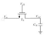
i am designing a track and hold circuit for +-0.1V, 200MHz input sampled at 1GHz. the track and hold circuit is not preceded by any buffer, although in some papers input buffers are used to drive the capacitor. so my first question is: is the input buffer really necessary to drive the cap? the AC current wouldn't be very large-around 50uA with a 0.5pF cap and small signal swing: icap=2pi*200M*0.1*0.5p.
i use cadence spectreRF to do the schematic simulation.
if i use ideal voltage source from AnalogLib to feed a sin signal directly to the input of the track and hold circuit, which would be the source/drain of the MOS switch, the transient response and the hamonic distortion at the output are acceptable.
but if i insert a 50Ohm resistor in series with the voltage source(or i directly use a port), spikes will show at the input of the circuit,and the transient and distortion will become worse. the output waveform hardly tracks the input signal during the tracking mode.
So my second question is: what is the right signal source to the input? is using the ideal signal source of any practical importance? should i consider of using AC coupling, a transformer? i really wish to avoid ac coupling, because this circuit should be wide band and i dont know how to set the parameters for a transformer.
thanks and regards,
swordsman
