jimito13
Advanced Member level 1
Dear forum members and experts,
I have some questions regarding the measurement of my taped-out active 3rd order butterworth filter.I am trying to extract the bode diagram of the filter.
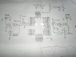
I attach a screenshot that contains the schematic of the board (PCB) where the filter is placed.
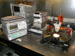
The instruments i make use of are :
1.)DC Power Supply
2.)Signal Generator
3.)Oscilloscope
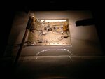
4.)Probe Station
I should note that the filter is not mathed at it's input and output and it's Zin and Zout are frequency dependent.
What i do to extract the bode plot is :
1.)Connect the power supply on the PCB (from DC aspect filter is ok,it absorbs the correct dc current from the supply of 1.2V and i have checked all voltages on the PCB and additionally no
short/open-circuits exist,so up to here everything is ok).
2.)I put the PCB on the probe station and i download one picoprobe needle in the one input of the filter and the other needle to the one output of the filter - i should mention that my filter is fully differential.
The needles are connected via their cable to the oscilloscope's channel 1 and 2 respectively.
I do this in order to avoid any de-embedding procedure caused by the baluns' , connectors' and transmission lines' losses.
3.)I connect via coaxial cable (50Ω) the signal generator to the input SMA connector of the chip.
4.)I notice the input and output signals on the oscilloscope's screen.
First question : Is my setup correct?
Second question : What amplitude should i inject from the ESG in order to take the measurements of the input's and output's amplitude and thus take the gain at each frequency?
Note : The filter has been designed for 10mV p-p maximun differential signal (-36dBm @ 50 Ω).
Because filter's Zin is frequency dependent i can't have a standard amplitude in filter's input since even ESG produces -36dBm let's say,this will be different in filter's input since impedance there changes with
frequency.
Additionally the input balun on the PCB has the following turns' ratio : Primary:Secondary = 1:8 .
Thanks in advance for any helpful answer.
Best Regards,
Jimito13
RFIC Designer
I have some questions regarding the measurement of my taped-out active 3rd order butterworth filter.I am trying to extract the bode diagram of the filter.
I attach a screenshot that contains the schematic of the board (PCB) where the filter is placed.
The instruments i make use of are :
1.)DC Power Supply
2.)Signal Generator
3.)Oscilloscope
4.)Probe Station
I should note that the filter is not mathed at it's input and output and it's Zin and Zout are frequency dependent.
What i do to extract the bode plot is :
1.)Connect the power supply on the PCB (from DC aspect filter is ok,it absorbs the correct dc current from the supply of 1.2V and i have checked all voltages on the PCB and additionally no
short/open-circuits exist,so up to here everything is ok).
2.)I put the PCB on the probe station and i download one picoprobe needle in the one input of the filter and the other needle to the one output of the filter - i should mention that my filter is fully differential.
The needles are connected via their cable to the oscilloscope's channel 1 and 2 respectively.
I do this in order to avoid any de-embedding procedure caused by the baluns' , connectors' and transmission lines' losses.
3.)I connect via coaxial cable (50Ω) the signal generator to the input SMA connector of the chip.
4.)I notice the input and output signals on the oscilloscope's screen.
First question : Is my setup correct?
Second question : What amplitude should i inject from the ESG in order to take the measurements of the input's and output's amplitude and thus take the gain at each frequency?
Note : The filter has been designed for 10mV p-p maximun differential signal (-36dBm @ 50 Ω).
Because filter's Zin is frequency dependent i can't have a standard amplitude in filter's input since even ESG produces -36dBm let's say,this will be different in filter's input since impedance there changes with
frequency.
Additionally the input balun on the PCB has the following turns' ratio : Primary:Secondary = 1:8 .
Thanks in advance for any helpful answer.
Best Regards,
Jimito13
RFIC Designer