Continue to Site

Welcome to EDAboard.com

Welcome to our site! EDAboard.com is an international Electronics Discussion Forum focused on EDA software, circuits, schematics, books, theory, papers, asic, pld, 8051, DSP, Network, RF, Analog Design, PCB, Service Manuals... and a whole lot more! To participate you need to register. Registration is free. Click here to register now.

Difference between PWM from Function Generator and from PWM VM

Status
Not open for further replies.

hridz

Junior Member level 3
Joined
Oct 11, 2011
Messages
27
Helped
0
Reputation
2
Reaction score
1
Trophy points
1,283
Location
Tezpur, India
Activity points
1,485
Hi guys

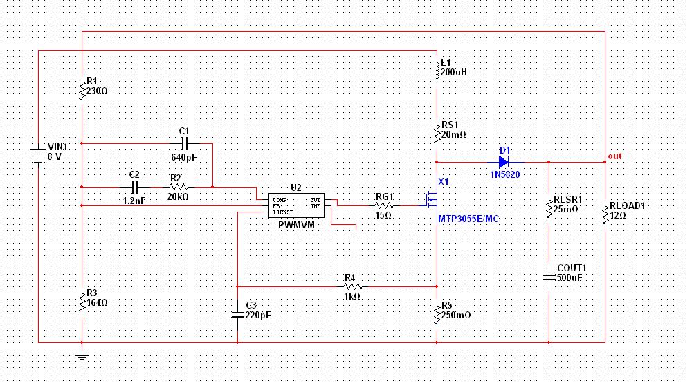
I want to know what is the difference between PWM from Function Generator and PWM from IC- PWM VM. I got a sample circuit of boost converter in NI multisim. where the PWM signal is taken from a PWM VM IC it is working very fine, but when i tried to give the PWM signal from a Function generator it is not working, output is coming less than the input. so what may be the reason????

with regards
hridz

I am attaching the circuit below...


there is a feedback loop on your function generator ?
 

sorry Gozaki, but I am not able to get you. I am not getting your point, what you want to say???
 

On your schematic here above. The network made from R1 R2 R3 C1 C2 allows U2 to know what's going on on the output and to react to variations. This is called "regulation". Using your function generator, i think you don't have this regulation anymore.
 
  • Like
Reactions: hridz

    hridz

    Points: 2
    Helpful Answer Positive Rating
thanks. now if i want to give this PWM from microcontroller then do i need such type of a regulation circuit or what?? because i want to control the output of the converter using PWM from microcontroller.
 

yes ! Look for pid regulation.
 

It's not clear what you mean by "PWM from function generator", thus it's hard to guess which problems you may have faced applying it. The shown IC would be regularly named a boost converter controller. As long as you don't need voltage regulation or current limiting, a fixed duty cycle square wave can control a boost converter as well.

Using a SPICE simulator like Multisim, you can see more than just the output voltage. You should be able to determine the differences in circuit operation yourself.
 

Status
Not open for further replies.

Part and Inventory Search

Welcome to EDABoard.com

Sponsor

Back
Top