Continue to Site

Welcome to EDAboard.com

Welcome to our site! EDAboard.com is an international Electronics Discussion Forum focused on EDA software, circuits, schematics, books, theory, papers, asic, pld, 8051, DSP, Network, RF, Analog Design, PCB, Service Manuals... and a whole lot more! To participate you need to register. Registration is free. Click here to register now.

Buck converter problems

Status
Not open for further replies.

BurnIt0017

Newbie level 6
Joined
Mar 13, 2010
Messages
14
Helped
0
Reputation
0
Reaction score
0
Trophy points
1,281
Location
earth
Activity points
1,404
videos of my MPPT project


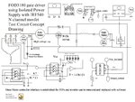
Hi, I designing a MPPT controller to use with a small wind turbine. If the micro is removed from the MPPT a buck converter remain.

AC voltage from a permanent magnet alternator is converted to DC using a bridge rectifier. Some basic data of DC values at different RPM.

Recorded data without circuit at Vin:
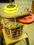
3 phase Star, 12 coil per phase, phase to phase resistance = 7.7 ohms
RPM, Voc, Voc with cap at input

100, 25, 28
150, 36, 39
200, 50, 50
250, 60, 64
300, 73, 78
(all voltage measurements are DC values)


Problems encounter during first phase of testing:

When measure current the DMV would over heat and stop working. Searching for method to measure high current for long periods of time.

The 555 timer has positive and negative voltage spikes. Is there a solution to dampen the voltage spikes?

Searching for solutions, comments welcome.

I am using a 12 volt deep battery as a test load.
 

Attachments

  • FOD3180testCircuitConcept.JPG
    FOD3180testCircuitConcept.JPG
    114 KB · Views: 74
  • PMA.jpg
    PMA.jpg
    119.2 KB · Views: 56
  • a1.jpg
    a1.jpg
    127.8 KB · Views: 57
Last edited:

1. Please test your test equipment and your knowledge before using it on the big project. If you allow your DVM to overheat, you apparently know nothing about its specifications or how to correctly measure voltage and current. Have you heard about analog ammeters? Or shunt resistors to use for current measurement?
2. A 555 timer if connected correctly generates no spikes. Have you used a 100 uF blocking capacitor across the DC input voltage for it? You can dampen the spikes but first learn how to operate it correctly and not generate spikes. How good are you in using an oscilloscope- using a bad probe can cause spikes, too.
3. Do not use "a battery" as a test load. A load on which you should measure what your generator generates should be a high-power resistor. Only knowing well your source it will be a time to use it for battery charging. Charging a battery requires to meet carefully its specifications: the voltage must be limited as well as the current.
4. A car alternator not only has a rectifier in it, also it has a regulator to properly charge the battery. I would test the alternator-battery system on a typical engine before mounting it on your wind propeller. Do you know its RPM and torque? An alternator needs those two to fall within certain limits to operate properly. This is why cars need a transmission while the engine's RPM are good between e.g. 1500-3500 RPM.
 
1.

The digital multimeters I've owned all have a 10A range. Inside I have seen a shunt bridging the posts for 10A. It's a thick wire about 1 inch long.

Does yours have this? Are the solder joints substantial and well-joined? A poor solder joint may have some resistance, causing it to generate heat when a lot of amps go through it.

2.

To monitor high current long-term, I obtained the 'inductive' (it's really more like a compass) current meters, from J.C. Whitney auto parts warehouse. You place it against the wire and the magnetized needle moves. Two scales: 0 to 100A, or 0 to 600A. Resolution is a few amps, but you may get more sensitivity if you were to magnetize the needle to a higher degree, and position the meter as close to the wire as possible.

Also suitable is an ammeter made for dashboard installations.
 
Hi, there is a first time for everything. I have tested the VAWT and the best I could get out it was 9 amps @ wind speed of 40 MPH. Basically the faster you spin the PMA the more it acts like a electric brake. Using the buck converter I can manually spin the PMA and the output is 4 amps using a 12 voltage halogen as a test load. So the circuit will improve the turbines output. The 12 volt battery is being used as test load because the output of the PMA output changes when using a resistive load at the same RPMs. Thanks for the information. I have ordered new parts and some analog amp meters with shunts. I will post results when available.
 

Hi, there is a first time for everything. I have tested the VAWT and the best I could get out it was 9 amps @ wind speed of 40 MPH. Basically the faster you spin the PMA the more it acts like a electric brake. Using the buck converter I can manually spin the PMA and the output is 4 amps using a 12 voltage halogen as a test load. So the circuit will improve the turbines output. The 12 volt battery is being used as test load because the output of the PMA output changes when using a resistive load at the same RPMs. Thanks for the information. I have ordered new parts and some analog amp meters with shunts. I will post results when available.

Okay, I wish you a good luck!
I also like experimenting but I prefer dividing my projects in parts I can test well first, then it is easier to predict the actions of the full system. If you use a battery as a load, it behaves differently when full and when charged, and you can damage it by overload.
The car electric system has been designed during many years, and gradually improved with various engine parameters and various loads. Before attempting to improve it, I would try to operate it as it is if your propeller RPM and torque are similar to engine's. BTW, a Halogen bulb is also not the best load.
In your schematic I do not see the original alternator regulator which stabilizes the voltage output while protecting the battery. I would stay with the verified blocks and improve them only when needed.
 

Hi, the final system will have a dump load controller that will monitor the battery voltage and transfer the current to a resistor bank when a preset voltage is reached. They are low cost and commercially available. Thanks again.
 

Status
Not open for further replies.

Similar threads

Part and Inventory Search

Welcome to EDABoard.com

Sponsor

Back
Top