Continue to Site

Welcome to EDAboard.com

Welcome to our site! EDAboard.com is an international Electronics Discussion Forum focused on EDA software, circuits, schematics, books, theory, papers, asic, pld, 8051, DSP, Network, RF, Analog Design, PCB, Service Manuals... and a whole lot more! To participate you need to register. Registration is free. Click here to register now.

Why the measure results are not the same by cable and pcb diff_feed

Status
Not open for further replies.

rf1008

Full Member level 2
Joined
Mar 30, 2012
Messages
129
Helped
7
Reputation
14
Reaction score
7
Trophy points
1,298
Activity points
2,219
Hi all,

I used two-port VNA to measure DUT's impedance,and i can get S11/S22/S21/S12.

The measurement is done by dual coaxial pigtail and get some data,redo by PCB pigtails and also get some data. but i fond the datum are not the same,for example,Z11 from the VNA is 10-j100.2 by coaxial method,but Z11 from the VNA is 10.1-j140.5 by PCB method. The real parts are very similar but the imag parts are different very much.

Calibrations are done well and also the ports extensions are done well separately for two methods. Why the imag parts are so different.It's an easy measurement, coaxial cable is 50 Ohm and PCB trace is also 50 Ohm, length is short.

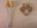
Attached picture is the coaxial pigtail and PCB pigtail. thanks a lot!
 

Attachments

  • IMAG0012a.jpg
    IMAG0012a.jpg
    97.4 KB · Views: 107

Hi,

one of the reason could be you didn't take in consideration the electric length of the coaxial pigtail, after you maked the calibrations.
Another reason could be the influence of the PCB on RF parameters .This is because a trace on the PCB is similary with a transmision line and this it means there is a parasitic capacitance and inductance that influence the imaginary impedance at the output.
To have good result I sugest you to meassure with the help of the 2 coaxial cables and see wich is there electric length(for this, you have a button on the VNA that help you to see the electric length.Notes that electric length should be meassure after you have the calibration).

Good luck and keep in touch with this problem
 

Hi,

one of the reason could be you didn't take in consideration the electric length of the coaxial pigtail, after you maked the calibrations.
Another reason could be the influence of the PCB on RF parameters .This is because a trace on the PCB is similary with a transmision line and this it means there is a parasitic capacitance and inductance that influence the imaginary impedance at the output.
To have good result I sugest you to meassure with the help of the 2 coaxial cables and see wich is there electric length(for this, you have a button on the VNA that help you to see the electric length.Notes that electric length should be meassure after you have the calibration).


Good luck and keep in touch with this problem


thanks~!

Length of the coaxial cable has been calibrated after OPEN/SHORT/LOAD calibration. So i can't believe any problem is there.
For the PCB method, the measured impedance is very similar to the DUT's impedance which is known before measurement, then i believe it's reliable. But why the coaxial method get wrong result????
 

PCB Dielectric Coefficient for FR4 is not constant by frequency so that the manufacturers give this coeffcient for certain frequency,temperature and relative humidity.Therefore the dielectric coeffcient which you used to calculate characteristic impedance for PCB traces migh not be correct.
In additional to, if the operating fequency is sufficiently high, this coefficient may vary very much with frequency that's why you traces can have a different impedance.
Finally, manufacturing tolerances may be high and this impact- especially at very high frequencies- trace caharacteristic impedance.
Rigid cables are more reliable and trustable compare to PCB traces.
 

Would you mind posting the Z11 vs. frequency trace? And, how do you connect the lines to your DUT? What's the dimension of the DUT compared to the PCB trace? You calibrated out the electrical length for both methods respectively, right?
 

Getting a good ground with a pigtail is difficult. Usually I fray the ground and try to leave it about the same length as the center conductor. Then solder to ground as close as possible to where the center conductor is soldered. As the frequency gets higher, it gets more difficult, and greater error.
 

PCB Dielectric Coefficient for FR4 is not constant by frequency so that the manufacturers give this coeffcient for certain frequency,temperature and relative humidity.Therefore the dielectric coeffcient which you used to calculate characteristic impedance for PCB traces migh not be correct.
In additional to, if the operating fequency is sufficiently high, this coefficient may vary very much with frequency that's why you traces can have a different impedance.
Finally, manufacturing tolerances may be high and this impact- especially at very high frequencies- trace caharacteristic impedance.
Rigid cables are more reliable and trustable compare to PCB traces.

Yes,i agree with you well. But my operation freq.is only 900MHz and the PCB/manufacturing impacts will be very small.

---------- Post added at 16:51 ---------- Previous post was at 15:54 ----------

Would you mind posting the Z11 vs. frequency trace? And, how do you connect the lines to your DUT? What's the dimension of the DUT compared to the PCB trace? You calibrated out the electrical length for both methods respectively, right?

Thanks to all.
 
Last edited:

Status
Not open for further replies.

Part and Inventory Search

Welcome to EDABoard.com

Sponsor

Back
Top