Continue to Site

Welcome to EDAboard.com

Welcome to our site! EDAboard.com is an international Electronics Discussion Forum focused on EDA software, circuits, schematics, books, theory, papers, asic, pld, 8051, DSP, Network, RF, Analog Design, PCB, Service Manuals... and a whole lot more! To participate you need to register. Registration is free. Click here to register now.

Not enough information on LEDs to match the parallel currents with resistors

Status
Not open for further replies.

grizedale

Advanced Member level 3
Joined
Jun 13, 2011
Messages
838
Helped
17
Reputation
34
Reaction score
17
Trophy points
1,298
Activity points
8,804
Hello, we are putting Cree XPEWHT (white) LEDs three-in-parallel, and wish to match the currents to within +/-20%
The total current through each LED would be 425mA if perfectly matched.

However, the information that we need to match the LEDs is in the form of I-V curves which are simply not provided in the XPEWHT datasheet.

The graph we need is as in Figure 3, Page 2 of the following application note................

Figure 3, Page 2
**broken link removed**

LED datasheet

XPEWHT LEDs
**broken link removed**


..this datasheet clearly does not provide anything like figure 3 , page 2 of the app note....Page 8 of the datasheet shows an i-v curve for the white led, but its just one curve, and thats not enough for us.

-So how are we supposed to mathc up the LED currents.

The LEDs are driven by a buck led driver as follows....( the total average current from the buck's output diode is 2.55 Amps)

R65 COMPTOR BUK.jpg

(the idea is to use the absolute minimum resistor value which gives us the +/-20% variance, so that we keep efficiency as high as possible)
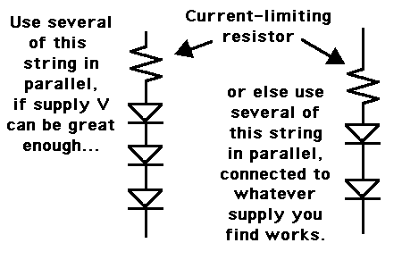
 

It becomes unwieldy to use led's in parallel. Instead, try to put as many led's as you can into each string...

Because the more led's in a string, the fewer strings you will need, and the fewer current-limiting resistors you will need.

If your supply V is not high enough to turn on 4 in series, then see if it can turn on 3 in series.
If it cannot turn on 3, then 2 it will have to be.

Per diagram:

78_1336265811.gif
 

i am inclined to kind-of agree with you, but the buck topology means we cannot do the leds-in-series thing. (at least not more than two leds in series)

We need buck , as its the cheapest topology, and unlike in boost smps's, the buck fet offers a degree of load short circuit protection.......not only that, but buck does not need output overvoltage protection in the event of open_led.

So buck it is, however, how do we go about selecting the series resistors....again they need to be as small as possible for +/-20% current matching
 

Even if you can't put all LEDs in one series string, you can still avoid putting LEDs directly in parallel. Have six strings of two LEDs plus a resistor in series, and then put them all in parallel, then in series with the current sense resistor. Should improve current sharing significantly, the only downside being that you need six resistors instead of four. Efficiency shouldn't be affected at all.

Other than that, the only advice I can give is to try and thermally couple the LEDs together, so that their negative tempco doesn't cause thermal runaway.
 
As you know, when led's are in parallel, one rogue led can hog the current. Or one rogue led can remain dim due to having a higher forward threshold than the other led's. There is no resistor value that can automatically prevent such faults when led's are in parallel.

If you intend to run parallel led's, then they will need to be manufactured to a close tolerance, in order to prevent the above faults.

Looking at your schematic, it seems to me that your R1 and R3 are superfluous. R5 appears to be a sense resistor.

That leaves R2 and R4. They can be identical values. Rather than predict what value, you can adjust them to allow the desired current while the buck converter is driving the entire load.

Since you desire a tolerance of 20 percent, R2 and R4 can have a tolerance of 20 percent. However 10 percent tolerance is much more common. Again, no resistor value exists that will prevent unbalanced operation among parallel led's.
 

If it were me, I would arrange the 12 LEDs in 6 branches each consisting of 2 LEDs in series and a limiting resistor connected to ground. Then, I will take the feedback signal from these six resistors (via another 6 resistors going to the IN+ of opamp that will act like an adder).

Added_1:
Of course, if the application is critical the six feedback voltages could also be monitored in case a fault occurs on one or more branches or the current balance deviates more than expected.

Added_2:
I remember now, a friend who had the same problem but his sets of 3 parallel LEDs each were already installed and relatively far from the supply (supplies). I hope this is not your case.

Added_3:
About the efficiency, it will be the same as long "Vout" is constant because:
P_resistors = (Vout - V_leds) * I_leds
Pin = Vout * I_leds
And both are constant.
V_leds = 2 * V_led
I_leds = 6 * I_led

Added_3:
To get a higher efficiency a switched mode constant current supply would be needed hence there will be no need for current limiting resistors in the first place.
 
Last edited:

Status
Not open for further replies.

Part and Inventory Search

Welcome to EDABoard.com

Sponsor

Back
Top