Continue to Site

Welcome to EDAboard.com

Welcome to our site! EDAboard.com is an international Electronics Discussion Forum focused on EDA software, circuits, schematics, books, theory, papers, asic, pld, 8051, DSP, Network, RF, Analog Design, PCB, Service Manuals... and a whole lot more! To participate you need to register. Registration is free. Click here to register now.

help needed for Phase Shifter conversion to single supply

Status
Not open for further replies.

graygem

Member level 1
Joined
Sep 21, 2010
Messages
33
Helped
0
Reputation
0
Reaction score
0
Trophy points
1,286
Activity points
1,508
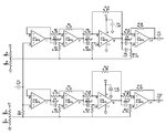
I have this circuit for a phase shifter using dual supply. I want to make one for single supply. Below is my take. Any help with supply conversion and phase shift calculations are appreciated. I don't quite understand how the frequency points are chosen. This circuit, if my math is right, has frequency points at:
IC1B= 3386.28Hz
IC1C= 497.98Hz
IC1D= 49.8Hz

IC2B= 13912.15Hz
IC2C= 1396.83Hz
IC2D= 201.56Hz

Thank you
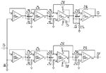
HT_Phase Shift.jpg

HT_Phase Shift_Single Supply.jpg
 

Re: help nneded for Phase Shifter conversion to single supply

You need to provide a "virtual ground" at Vdd/2 for all signal ground nodes and input/output AC coupling.

The calculation seems correct: f(90deg) = 1/(2piRC)
 

Re: help nneded for Phase Shifter conversion to single supply

The classic way would be to remove any earths from your PSU, so now its floating + -. Wire two resistors in series across it with a decoupling capacitor across each one (> 100MF) - look out for the polarity. Earth the junction of the resistors as your "centre tap". If you cannot tinker with the earthing arrangements of the power supply, then the phase shifting kit will have to be "floated", i.e. any wire which went to earth will have to be joined to a supply centre tap (as above) and all earths connected to metalwork, I/O sockets etc must also so be removed. Now looking at your inputs and outputs, they used to be at earth potential now they are at 1/2 Vcc potential so any input/output coupling capacitors must be suitablely polarisd.
Is this a +- 90 degree phase network for SSB?
Frank
 

Re: help nneded for Phase Shifter conversion to single supply

You need to provide a "virtual ground" at Vdd/2 for all signal ground nodes and input/output AC coupling.
I provided Virtual ground with the two 100K voltage dividers and I thought that the original C1, C7, & C12 would provide the I/O AC coupling. Or do I need capacitors between the all-pass filters themselves?

Is this a +- 90 degree phase network for SSB?
Frank

Sorry, I don't know what SSB is. This is for an audio project I'm doing on my own.
Also, I did not put the extra 100uF Caps in for the voltage dividers because they will be right next to the 100uF Supply caps, which I forgot to add to the schematic.
What tolerance resistors and capacitors should I use?

Thank you, so far.
 

Re: help nneded for Phase Shifter conversion to single supply

You are right, AC coupling is already there. The virtual ground don't need to carry DC current, so 100k + 100k is O.K. A larger bypass capcitor should be connected to negative supply, e.g. 10 - 100 uF.
 

Re: help nneded for Phase Shifter conversion to single supply

Using these frequency points, what is the frequency range? And how is it figured?
 

Re: help nneded for Phase Shifter conversion to single supply

I was under the impression you know what you are doing. According to the nature of the approximative differential phase shifter, the "frequency points" can be tuned to achieve an intended phase characteristic. The quality of the 3+3 all-pass design isn't mind blowing. There seems to be a systematic offset, or one of the frequency points has been calculated incorrectly. Phase shifters for wide band audio I have seen before, e.g used in SSB "feedback killers" had 6+6 to 8+8 stages.


Attachments

  • phase shifter.zip
    8.7 KB · Views: 47

Re: help nneded for Phase Shifter conversion to single supply

What would ever give you the impression I knew what I was doing? If I did, why would I need to ask for help? Anyway, I'm learning, thus asking for help trying to understand this phase shifter. As I said, I have the phase shifter circuit, it's not a standalone and I know it's only a 3+3. I didn't say I was building the original from scratch. The circuit is dual supply and I wanted a single supply, to use in something else. I know the math for the all pass filters, I just don't know how to figure the bandwidth for this particular circuit. I can use J-TEK's all pass filter designer program to calculate for using all the same capacitor.
 

Re: help nneded for Phase Shifter conversion to single supply

I just don't know how to figure the bandwidth for this particular circuit.
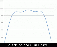
FvM's graph shows the differential phase shift vs frequency. To get more details about the performance, you could use software such as SIMetrix/SIMPLIS to simulate the circuit. That would also let you investigate the effect of changing component values.
 

Re: help nneded for Phase Shifter conversion to single supply

What would ever give you the impression I knew what I was doing?
Mainly the fact, that you didn't mention what you want to achieve with the circuit, as if you considered the circuit purpose and the required phase accuracy an obvious thing.

Of course it isn't obvious. The application requirements, intended phase accuracy and frequency range of interest should be known to start with the design.

I just don't know how to figure the bandwidth for this particular circuit.
Seeing the calculations provided by the said tool , I wonder what you are actually asking for?

If it's the problem to calculate the phase response for a given set of RC values, just plugin the known phase characteristic of an allpass to a spread sheet calculator, as I did in my Excel example.

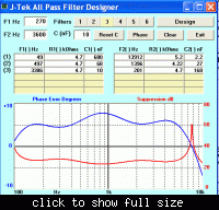
P.S.: You just didn't thoroughly try with J-TEK calaculator. It can do what you want:

 
Last edited:

Re: help nneded for Phase Shifter conversion to single supply

First, thank you for helping me, I really do appreciate it. I did not realize the J-TEK calc would do that until I saw your pic and stooped to figure it out.
 

Status
Not open for further replies.

Part and Inventory Search

Welcome to EDABoard.com

Sponsor

Back
Top