Continue to Site

Welcome to EDAboard.com

Welcome to our site! EDAboard.com is an international Electronics Discussion Forum focused on EDA software, circuits, schematics, books, theory, papers, asic, pld, 8051, DSP, Network, RF, Analog Design, PCB, Service Manuals... and a whole lot more! To participate you need to register. Registration is free. Click here to register now.

LM2576 can not load the current 3 Amp max

Status
Not open for further replies.

electronion

Newbie level 6
Joined
Nov 21, 2011
Messages
12
Helped
1
Reputation
2
Reaction score
0
Trophy points
1,281
Activity points
1,369
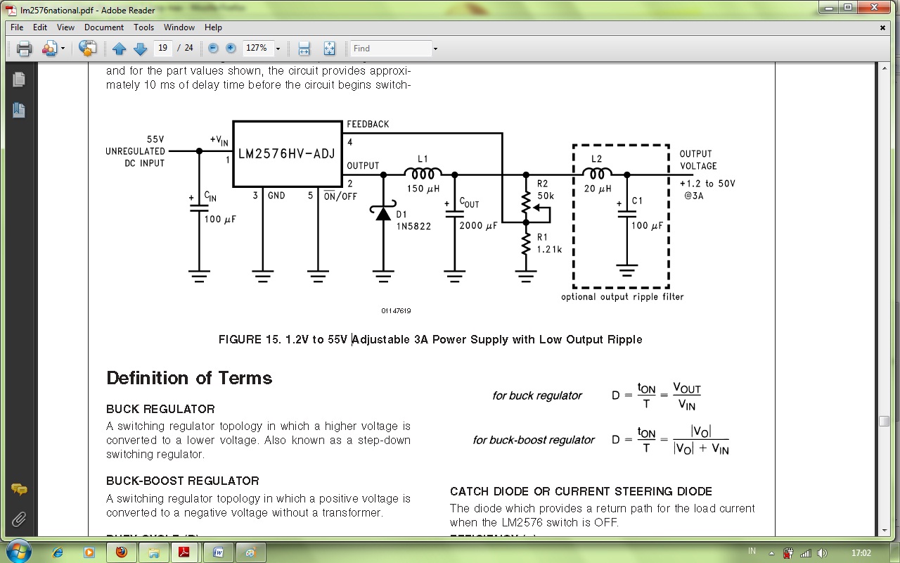
I have built my own power supply with lm2576 adj. & 3 Amp max load.. but it can't drive load current until 3 Amp max..
When I connect the 10 ohm resistor with 30 Vdc supply from the regulator.. it drops until 18 Volt.. and the load current becomes 1.8 Amp..
Why is it happen? it properly can drive until 3 Amp load current isn't it?

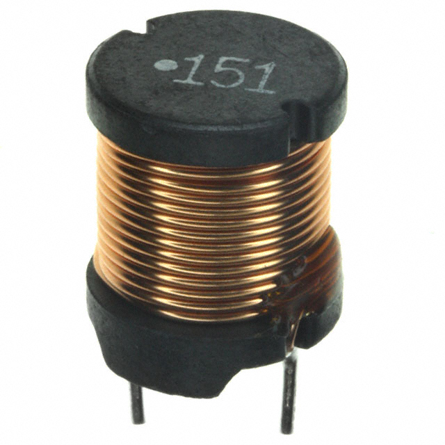
And one more, my inductor make creaking sound when I give the supply with that load.. Is it means that my inductor not enough able to handle the load current with bigger value?
 

which value inductor you are using?it should be 100uh and what is the output voltage?
 

I use 150uH inductor like the datasheet suggest..

like this one:


and the output voltage is adjustable from 1.2 - 35 Volt (I use LM2576T adj.)
 

which datasheet you referred i don't know.take look below test circuit its 100uh inductor there and try to find radio inductor i have same problems with chock type inductor as shown in your image.
 

Attachments

  • 2576.JPG
    2576.JPG
    104.2 KB · Views: 113

I think it is no problem using 150uH inductor but we must add the 2000 uF capacitor not 1000 like the schematic I use here..


REturn Loss of Cap may affect stability.
Can you scope current? 0.1Ω shunt?
Type of ESR /SRF on cap affects ripple. Check specs and test.

If you want to use an "active load " for testing , make a power transistor with heat sink and 0.01ohmshunt wire to ground.

Then show I and V with scope as X & Y mode then you can simulate 10 ohm with adjustable signal generator with dc & ac and/or pulses.

Also inductor may be microphonic with windings and current surges. Coating will reduce noise but also lower SRF.
 

I'm not an expert in switching voltage regulator, however i think you should check:

1. the current rating of the L1 inductor you are actually using
2. the stability of the input voltage when the load is applyed
3. the layout and the grounding of the board. These could by critical, once I experienced many problems due to bad layout (the component I used was different but the problems could be the same)
 

@electronion I believe you mentioned inductor current rating so I looked at the photo and found the part on digi-key library and it appears to be a TDK part which may be underrated for this 3A design.

I suggest a lower value of inductance ie 100 µH or higher rated current.

You can measure your current with a 50mΩ shunt (make one if not avail using magnet wire with same resistance then fold wire in half and wind so inductance cancels.) or use a proper shunt if you have.
https://media.digikey.com/pdf/Data Sheets/TDK PDFs/SL Series SL1215.pdf
https://www.digikey.ca/product-detail/en/SL1215-151K1R3-PF/445-3793-ND/1913657

If 3.4A rating is enough , this one has less R too and less stray noise since it is a torroid.
https://www.digikey.ca/product-detail/en/2114-H-RC/M8811-ND/775350
 
Last edited:

Status
Not open for further replies.

Similar threads

Part and Inventory Search

Welcome to EDABoard.com

Sponsor

Back
Top