Continue to Site

Welcome to EDAboard.com

Welcome to our site! EDAboard.com is an international Electronics Discussion Forum focused on EDA software, circuits, schematics, books, theory, papers, asic, pld, 8051, DSP, Network, RF, Analog Design, PCB, Service Manuals... and a whole lot more! To participate you need to register. Registration is free. Click here to register now.

strange behaviour of H bridge

Status
Not open for further replies.

anotherbrick

Full Member level 4
Joined
Jan 10, 2009
Messages
217
Helped
1
Reputation
2
Reaction score
1
Trophy points
1,298
Location
Istanbul , Turkey
Activity points
3,143
hello friends

I drive 24 V 10 amps DC brush motor with IRF540 H bridge
the gates are driven by IR2113s

I PWM the High side of Channel 1 and logic 1 to the Low side of channel 2
low side of channel 1 and high side of channel 2 is logic 0

VCC of IR2113 is 12 V by LM2575
duty of PWM is %30

when I lower the DC link voltage to 19 V the motor turns
when I raise the DC link voltage to 24 - 25 V the H bridge output is only 1 - 2 Volts by multimeter reading and motor doesnot turn

what am I doing wrong ?
 

Hello,

for clarity, please post your circuit. Do you have an oscilloscope to do measurements?
 

IR2113.jpg

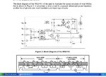
this is my circuit ( half of H bridge )
the DClink voltage is 24 V from 60 AH Accu ( charge is full )
the bootstrap cap is 1 uF and PWM frequency is 10 Khz with %30 duty
the bootstarp diode is UF4007

the microcontroler is STM32F103 and I checked with oscilloscope -> PWM signal is there
 

Hello,

This is just a part of your circuit, best is to post circuit of complete output stage.

How do the waveforms (gate and outputs) change when you increase the supply voltage? Is Vcc within the specs of the IC (and your application)?
 

I PWM the High side of Channel 1 and logic 1 to the Low side of channel 2
low side of channel 1 and high side of channel 2 is logic 0

I think your problem might be here. For the bootstrapping gate drivers to work properly, each H bridge should be driven with PWM (not with a continuous logic level). Trying to drive the high side of either half bridge continuously will result in the bootstrap capacitor losing its charge quickly. You can drive low side FETs continuously though without a problem.

Try giving proper PWM signals to both FETs in channel 1. That should help.
 

1) I PWM the high side already

2) I use 12 V for gate drive IC ( i.e VGS of mosfets are 12 V ) - should I use 15 V ?
 

What s the big secret posting half circuit
i looked at the data sheet i hope u didnt put your motor at load .
where did u see such a circuit and how did u decide load should be in this way ?
do u have a dual windings recersial special motor if so say so.
 

hello friends

I found a bug in my software - the PWM timings are now better
however the problem with the 24 Volt still going on

I watch the high side gate signal at the HO output of IR2113
when the PWM signal duty reaches appr. %10 from %0 at startup ( I make a 2 second ramp of PWM duty from %0 to %30 ) , the gate signal vanishes suddenly
however the PWM signal at the STM32 outputs are there

I suspected SD pin of IR2113 - I made the SD and VSS conections to the GND on the PCB thicker
however still same problem

what else can couse the vanishing of HO signal ?
does anybody have an idea ?
 
Last edited:

Same old same old ...u giving partial diagram asking for help
your circuit is for demonstration and general knowledge only and will never work if u apply a load where shown load.

vcc may be marginal so check it out
remove 24v and check pulse ho/vs....lo/com.
check out the link this is what u must look for A REAL APPLICATION OF THE CIRCUIT and tell us what option u r using , and post answer is it something like this ?
http://www.irf.com/technical-info/appnotes/an-978.pdf
ir2110 app notes.JPG
 

Attachments

  • ir2110 app notes.JPG
    ir2110 app notes.JPG
    269.8 KB · Views: 108
Last edited:

hello friends

Dselec - of course I built a full H-bridge - what I have post is only half of my circuit
I have not schematic designer in my computer thats why I copy-pasted the IR datasheet - why are you so angry at me ? I know that an H bridge has 4 transistors :smile:

here is what I have made ;

I have strengthen the traces on the PCB with extra wires GND --> Vss and COM pins - I have put extra short circuit between Vss and COM pins of IR2113

now it works - with no load at motor shaft - tomorow I will test with load at motor

thanks to everyone who commented on my question
 

Hello another i am not angry with u .
But posting half a diagram will result wrong answers or more questions .
More .... posting full will benefit others that may be doing what u did and your diagram will help them too.
If u see my link u will see u can work with 2 transistors (fig 28a & 31)so if u decide to use one of the options in my link by telling us we will benefit as well.
good luck
dselec
 

@anotherbrick: We take time to dive into your problems. Why not make it easier for us to do that? It increases the probability that we can give you useful feedback
 

I drive 24 V 10 amps DC brush motor with IRF540 H bridge
the gates are driven by IR2113s

I PWM the High side of Channel 1 and logic 1 to the Low side of channel 2
low side of channel 1 and high side of channel 2 is logic 0

I am sorry but in my first message I thought that it is clear for the readers that I built a full H bridge with 4 mostefs

sorry I have not a schematic designer like proteus - thats why I copy-pasted IR datasheet
 

I still dont understand brick ..dont u have a scanner or internet camera /phone camera or any other means to copy your full diagram and post it have u checked my link does your circuit similar to many diagrams there.
 

26042012022.jpg

hello dear friends ,

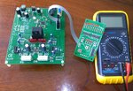
here is the photo of my circuit - this is a handicapped electric wheelchair control
I have 2 full H-bridges driving 2 DC 24 V motors ( left and right )

in the past week I have solved the problems which I have asked in my previous posts
the bridges are functioning well - they drive the motors

however there is one problem

if I drive both motors in positive direction the chair is moving forward
for turning to right for example I shut down right H bridge ( logic 0 to all FETs ) and give % 25 duty to left H bridge
for turnign left the opposite

if I want to turn right or left from zero speed it is ok
however if I want to turn left ( or right ) while moving forward ( with %70 duty for example )

( my suspicion ) the driving H-bridge waits until the motor EMF ( caused by the inertia of the load ) is below the corresponding PWM value ( left turning % 25 duty )
and just after that the motor is driven with current

I want a smooth transfer of motion from forward to left ( or right )
however the chair loses its forward speed about 1.5 seconds and then just after that moves to left

my question - why the H-bridge is not driving the motor until EMF = % 25 duty is reached ?
why it is not motoring as soon as I give % 25 duty to left ( or right ) ?
 
Last edited:

Status
Not open for further replies.

Part and Inventory Search

Welcome to EDABoard.com

Sponsor

Back
Top