anuragmash
Junior Member level 1
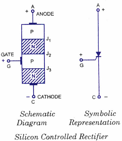
1.) When the SCR is in the forward conduction mode and positive gate signal is applied to the p region of junction j2 then why is it that after a threshhold value is reached the gate signal can be switched off?
2.) Won't the J2 become reverse biased again?
3.) In a transistor (BJT) a constant 0.7 volts is applied to the emitter and base junction when the external voltage is applied to collector and a steady flow is established can we not turn of the emitter-base voltage?
4.) Are not both the situations identical?
"Thyristor, the name is derived from a combination of two words THYRatron and transISTOR."
5.) What happens when we apply a gate signal? Do electrons get injected into the junction J2 and breakdown the junction i.e. push the other electrons (repel) forward as they are excited by another voltage?
---------- Post added at 09:13 ---------- Previous post was at 07:55 ----------
I researched around a bit and found out that the SCR accomplishes this (gate turn off) by regenerative action i.e even when the gate is turned off SCR conducts so how does it actually accomplish this... Please don't give me the 2 transistor analogy, I want to know the physicists viewpoint on this....