basofias
Junior Member level 2
Hello people,
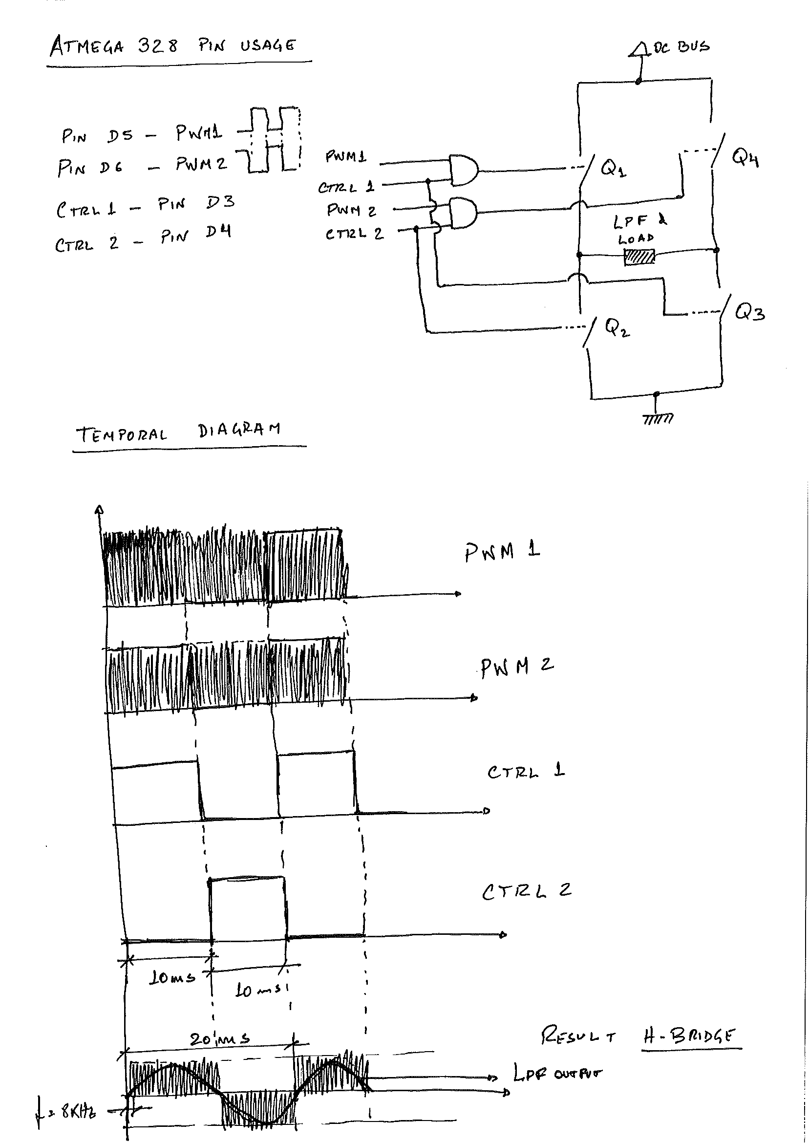
I´m building at this moment a DC-AC pure sinewave inverter, and i have some questions in the power conversion in a tri level PWM architecture, for driving a H-bridge (Mosfet or IGBT).
- The first question is:
I am using a microcontroler ATMEGA328 for generation a two independent PWM signals, based on this code:
The PWM signals are complementary!
For tri level PWM we should have something similar to this:

But we have only 2 independent PWM in thir format:
View attachment TEK0000.BMP View attachment TEK0002.BMP
How we can split our PWM signals to match with the first SPWM1 & SPWM2 picture???
Thanks,
Best regards
Basofias
:roll::roll::roll::roll::roll::roll:
I´m building at this moment a DC-AC pure sinewave inverter, and i have some questions in the power conversion in a tri level PWM architecture, for driving a H-bridge (Mosfet or IGBT).
- The first question is:
I am using a microcontroler ATMEGA328 for generation a two independent PWM signals, based on this code:
The PWM signals are complementary!
Code:
/* based on code by srnka
 Generating of PWM signals for single phase inverter circuit
 generating of sine signals with freq from 33 Hz to 61 Hz
 output values: PWM signals on 2 PWM outputs: one inverted and one non-inverted
*/
int i;  //i...for cycle
int j=64; //for setting the correct number of steps for the selected frequency (initial is the nr. of samples at 61Hz)
int z=0; //for selecting the correct value from the sinetable
int x=0;  //frequency selector - setting initial freq to 61 Hz
int y=0;  //setting of loop counter
int s=30;  //this value is the speed of frequency changing - later it could be controlled by a variable resistor connected to analog input
float phase;      // For calculating value of phase
//setting of sin table for half-period of 8 frequencies

//      steps     frequency
//sin1	64	61,03515625
//sin2	70	55,80357143
sin3	78	50,08012821
//sin4	86	45,42151163
//sin5	94	41,55585106
//sin6	102	38,29656863
//sin7	110	35,51136364
//sin8	118	33,10381356

//======================:.-"-.:    S I N E T A B L E   :.-"-.:====================================
//values are calculated from sinus values and amplidude is corrected based on tests
int sinus[]= {127, 133, 140, 146, 152, 158, 164, 170, 176, 182, 188, 193, 199, 204, 209, 213,
      218, 222, 226, 230, 234, 237, 240, 243, 245, 247, 249, 251, 252, 253, 254, 254, 254, 254, 253,
      252, 251, 249, 247, 245, 243, 240, 237, 234, 230, 226, 222, 218, 213, 209, 204, 199, 193, 188,
      182, 176, 170, 164, 158, 152, 146, 140, 133, 127,

      127, 132, 138, 143, 148, 153, 158, 163, 168, 173, 178, 183, 187, 192, 196, 200, 204, 208, 212,
      215, 219, 222, 225, 227, 230, 232, 234, 236, 238, 239, 241, 242, 242, 243, 243, 243, 243, 242,
      242, 241, 239, 238, 236, 234, 232, 230, 227, 225, 222, 219, 215, 212, 208, 204, 200, 196, 192,
      187, 183, 178, 173, 168, 163, 158, 153, 148, 143, 138, 132, 127,

      127, 131, 136, 140, 144, 149, 153, 157, 161, 165, 169, 173, 177, 181, 185, 188, 192, 195, 199,
      202, 205, 208, 211, 213, 216, 218, 220, 222, 224, 226, 228, 229, 230, 231, 232, 233, 233, 234,
      234, 234, 234, 233, 233, 232, 231, 230, 229, 228, 226, 224, 222, 220, 218, 216, 213, 211, 208,
      205, 202, 199, 195, 192, 188, 185, 181, 177, 173, 169, 165, 161, 157, 153, 149, 144, 140, 136,
      131, 127,

      127, 131, 134, 138, 142, 145, 149, 152, 156, 159, 163, 166, 169, 173, 176, 179, 182, 185, 188,
      191, 194, 196, 199, 201, 204, 206, 208, 210, 212, 214, 216, 217, 219, 220, 221, 222, 223, 224,
      225, 225, 226, 226, 226, 226, 226, 226, 225, 225, 224, 223, 222, 221, 220, 219, 217, 216, 214,
      212, 210, 208, 206, 204, 201, 199, 196, 194, 191, 188, 185, 182, 179, 176, 173, 169, 166, 163,
      159, 156, 152, 149, 145, 142, 138, 134, 131, 127,

      127, 130, 133, 136, 139, 142, 145, 148, 151, 154, 157, 160, 163, 166, 168, 171, 174, 176, 179,
      181, 184, 186, 189, 191, 193, 195, 197, 199, 201, 203, 204, 206, 207, 209, 210, 211, 212, 213,
      214, 215, 216, 216, 217, 217, 218, 218, 218, 218, 218, 218, 217, 217, 216, 216, 215, 214, 213,
      212, 211, 210, 209, 207, 206, 204, 203, 201, 199, 197, 195, 193, 191, 189, 186, 184, 181, 179,
      176, 174, 171, 168, 166, 163, 160, 157, 154, 151, 148, 145, 142, 139, 136, 133, 130, 127,

      127, 130, 132, 135, 137, 140, 142, 145, 147, 150, 152, 155, 157, 160, 162, 164, 167, 169, 171,
      173, 175, 177, 179, 181, 183, 185, 187, 189, 190, 192, 194, 195, 197, 198, 199, 201, 202, 203,
      204, 205, 206, 206, 207, 208, 208, 209, 209, 210, 210, 210, 210, 210, 210, 210, 210, 209, 209,
      208, 208, 207, 206, 206, 205, 204, 203, 202, 201, 199, 198, 197, 195, 194, 192, 190, 189, 187,
      185, 183, 181, 179, 177, 175, 173, 171, 169, 167, 164, 162, 160, 157, 155, 152, 150, 147, 145,
      142, 140, 137, 135, 132, 130, 127,

      127, 129, 131, 133, 136, 138, 140, 142, 144, 146, 148, 150, 152, 154, 156, 158, 160, 162, 164,
      166, 168, 170, 171, 173, 175, 176, 178, 180, 181, 183, 184, 185, 187, 188, 189, 190, 192, 193,
      194, 195, 196, 196, 197, 198, 199, 199, 200, 200, 201, 201, 201, 202, 202, 202, 202, 202, 202,
      202, 202, 201, 201, 201, 200, 200, 199, 199, 198, 197, 196, 196, 195, 194, 193, 192, 190, 189,
      188, 187, 185, 184, 183, 181, 180, 178, 176, 175, 173, 171, 170, 168, 166, 164, 162, 160, 158,
      156, 154, 152, 150, 148, 146, 144, 142, 140, 138, 136, 133, 131, 129, 127,

      127, 129, 131, 132, 134, 136, 138, 140, 141, 143, 145, 147, 148, 150, 152, 153, 155, 157, 158,
      160, 161, 163, 164, 166, 167, 169, 170, 171, 173, 174, 175, 177, 178, 179, 180, 181, 182, 183,
      184, 185, 186, 187, 188, 188, 189, 190, 190, 191, 191, 192, 192, 193, 193, 193, 194, 194, 194,
      194, 194, 194, 194, 194, 194, 194, 193, 193, 193, 192, 192, 191, 191, 190, 190, 189, 188, 188,
      187, 186, 185, 184, 183, 182, 181, 180, 179, 178, 177, 175, 174, 173, 171, 170, 169, 167, 166,
      164, 163, 161, 160, 158, 157, 155, 153, 152, 150, 148, 147, 145, 143, 141, 140, 138, 136, 134,
      132, 131, 129, 127};

//14 steps of frequency ramping (actually just 8 different freq. in loop)
int fbase[]={64,70,78,86,94,102,110,118,110,102,94,86,78,70};

//======================:.-"-.:    S E T U P   :.-"-.:============================================
void setup()
{


 //=====setting of timer0 for fast PWM method====
 //frequency PWM is fosc/(8*256) (by 16MHz oscil. = 7812,5)
 //timer 0, 8-bit timer, pins 5,6(+)   128us
 TCCR0A=0b10110011;   // generate inverted PWM signals in output
 TCCR0B=0b00000010;   // set of source of clock signal + prescaller fclk/8

 //setting of PWM ports 5 and 6 to output (one is inverted - frequency is the same all the time)
 pinMode(5,OUTPUT);
 pinMode(6,OUTPUT);

}

//======================:.-"-.:  M A I N   L O O P  :.-"-.:============================================
void loop()
{

 //when "2*s" number of loops are made, the frequency is changed
 //(2*s to get whole sine wave - 360deg, no matter what the value of "s" is,
 //since j is the number of steps in half of sine period (at startup it is set to 64, so the infinite loop can) start

  if(y==2*s*j)   //check if some frequency has been looped for 2*s times (since j is a number of steps in 1/2 period
   { x=x+1;     //here the frequency change is done with "x" (initial value is 0!)
   if(x==14){   //if x is higher than 13 i.e. when x==14 it needs to be set to 0 again
     x=0;}
   }

   j=fbase[x];   //setting the freq. to the selected one  / first the x=0, so j=64 (frequency is 61 Hz)
    //change of polarity
    TCCR0A = TCCR0A ^ 0b01010000;
   //cycle for half period
  for(i=0; i<j;i++)
  {
   //setting the correct "z" for the selected frequency
    if(j==64){                   //           61Hz
      z=i;
     }
    if(j==70){                  //           55Hz
      z=i+64;  //+64
     }
    if(j==78){
      z=i+134; //70+64          //            50Hz
     }
    if(j==86){
      z=i+212;  //78+70+64      //            45Hz
     }
    if(j==94){
      z=i+298; //86+78+70+64      //            42Hz
     }
    if(j==102){
      z=i+392; //94+86+78+70+64     //      38Hz
     }
   if(j==110){
      z=i+494; //102+94+86+78+70+64      // 35Hz
     }
    if(j==118){
      z=i+604; //110+102+94+86+78+70+64    //33Hz
     }
   //generating of value OCR0x, but output frequency is the same, since they are toggled outputs
   //(it's just that when one sine wave raises the other decreases)
    phase=sinus[z];
    OCR0A=byte(phase);
    OCR0B=byte(phase);

 }
 //******************************************************
 y=y++;  //loop counter
}
For tri level PWM we should have something similar to this:
But we have only 2 independent PWM in thir format:
View attachment TEK0000.BMP View attachment TEK0002.BMP
How we can split our PWM signals to match with the first SPWM1 & SPWM2 picture???
Thanks,
Best regards
Basofias
:roll::roll::roll::roll::roll::roll: