Continue to Site

Welcome to EDAboard.com

Welcome to our site! EDAboard.com is an international Electronics Discussion Forum focused on EDA software, circuits, schematics, books, theory, papers, asic, pld, 8051, DSP, Network, RF, Analog Design, PCB, Service Manuals... and a whole lot more! To participate you need to register. Registration is free. Click here to register now.

colpitt's oscillator using op-amp

Status
Not open for further replies.

iVenky

Advanced Member level 2
Joined
Jul 11, 2011
Messages
584
Helped
37
Reputation
76
Reaction score
35
Trophy points
1,318
Location
College Station, Texas
Activity points
6,124
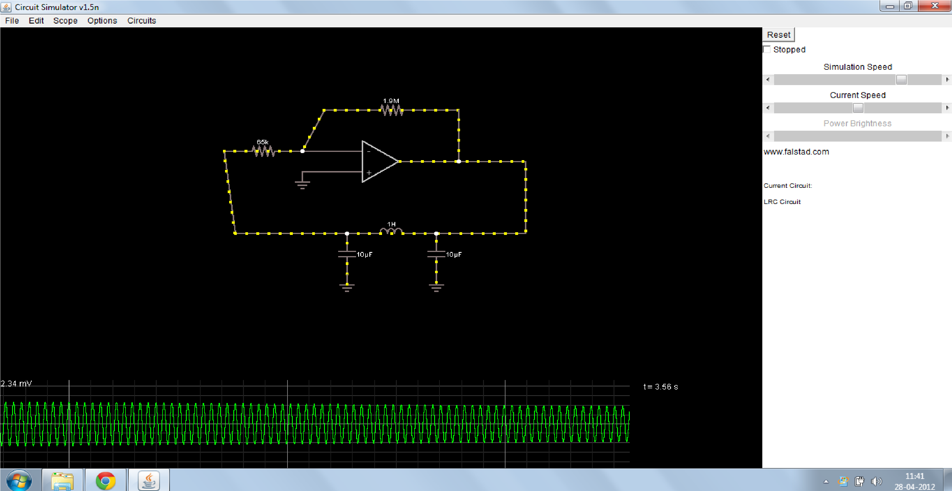
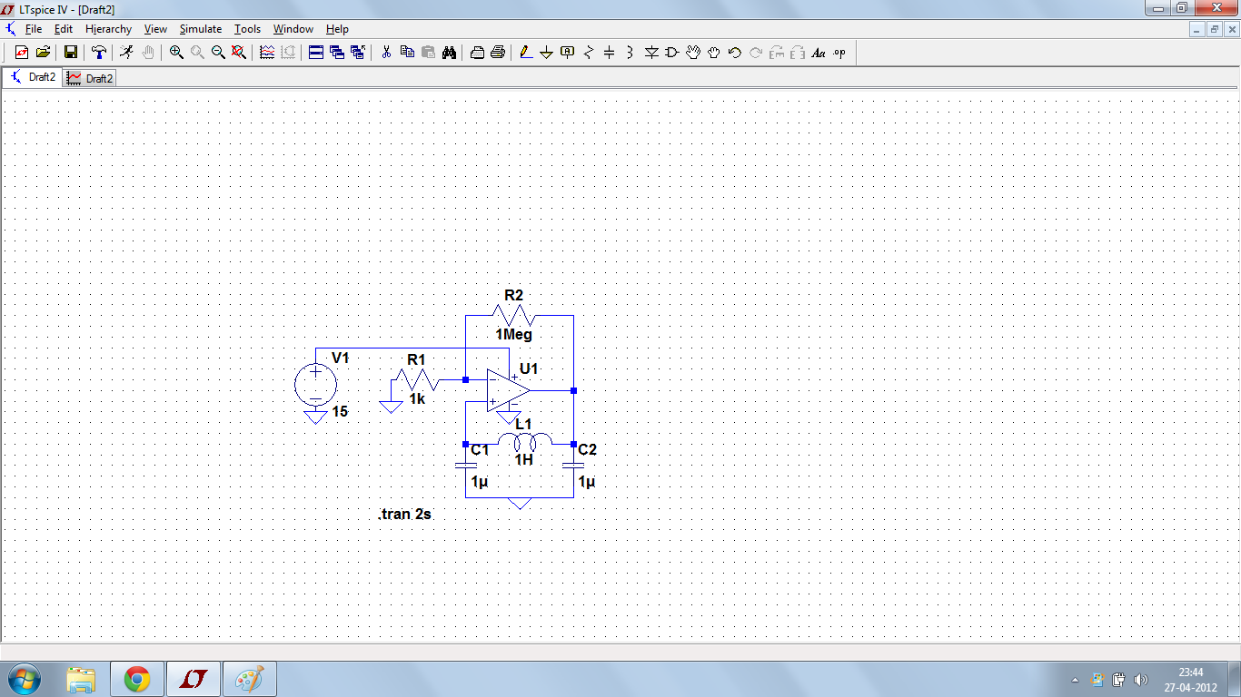
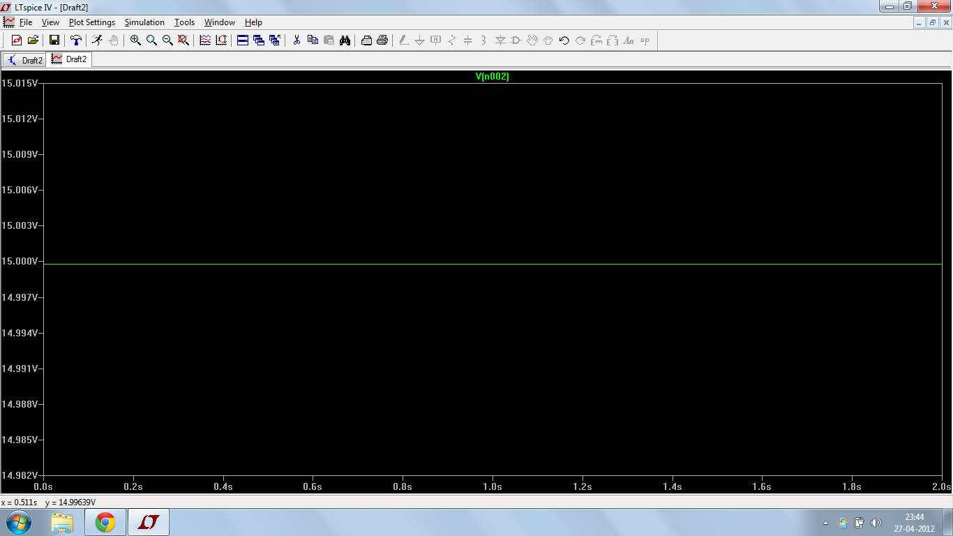
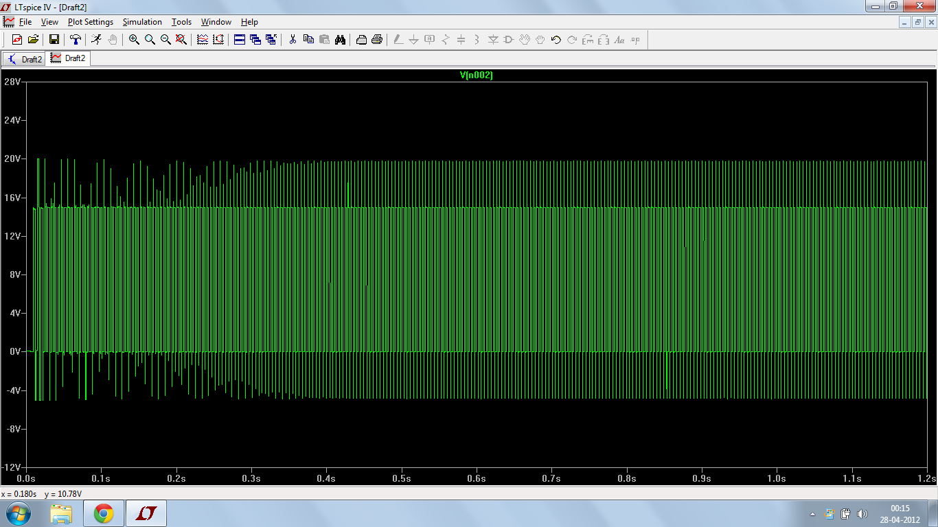
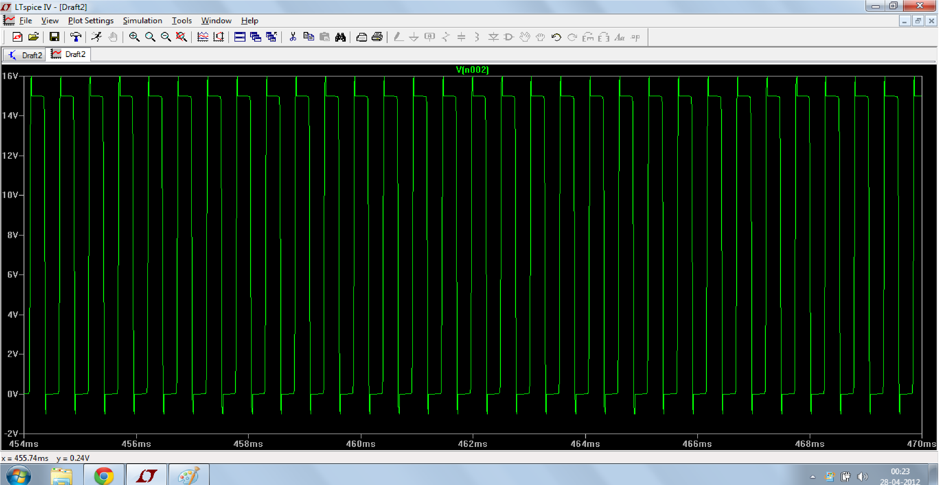
I am learning about oscillators right now. I know the basis of oscillators but I couldn't quite get it while doing those using op-amps. I simulated colpitt's oscillators using transistors by just giving the output to the C, L, C combination and again gave that back as input to the transistor. Now I tried it using op-amp. I got some doubts while doing that and I tentatively did that by connecting the output to C L C combination and gave that as input to the +ve terminal of op-amp- This is the place where I got confused. Where should I give the feedback to? positive or negative terminal of op-amp. I gave that to positive terminal I got nothing out of it (got supply voltage at the output). Here's the simulation images


What is actually happening when you give the feedback to the negative terminal and when you give the feedback to the positive terminal? What should I do to get the ouptut?


Thanks in advance.:-D:-D:-D
 

YOur design has +feedback for DC reverse +/- inputs on Op Amp and on + input connect to V+/2 with equal value R No need 1MΩ feedback R , thats only for Xtals. Also choose FET /CMOS OP amps for Rail to Rail inout and output.. or simply use CMOS inverter Logic gate.
 
I am learning about oscillators right now.
In this case, it would be a good idea to start evaluating known working oscillator circuits. The present one has a positive DC feedback and thus works as a latch. It can't oscillate.

You can change it to a slightly more reasonable construct by adding a highpass to the LC feedback path. Then it can oscillate, but the waveforms look dreadful.

There are at least these issues with the circuit besides the said DC feedback problem:
- Gain is much too high
- no stable oscillation condition
- the capacitor at the OP output is more or less useless, because it's shorted by the low impedance OP output.

Actually, it doesn't look like a regular Colpitts oscillator, which uses an inverting amplifier with some output impedance, and 180° phase shift provided by the LC circuit.
 
  • Like
Reactions: LvW

    LvW

    Points: 2
    Helpful Answer Positive Rating
In this case, it would be a good idea to start evaluating known working oscillator circuits. The present one has a positive DC feedback and thus works as a latch. It can't oscillate.

You can change it to a slightly more reasonable construct by adding a highpass to the LC feedback path. Then it can oscillate, but the waveforms look dreadful.

There are at least these issues with the circuit besides the said DC feedback problem:
- Gain is much too high
- no stable oscillation condition
- the capacitor at the OP output is more or less useless, because it's shorted by the low impedance OP output.

Actually, it doesn't look like a regular Colpitts oscillator, which uses an inverting amplifier with some output impedance, and 180° phase shift provided by the LC circuit.


I did exactly what you said and it is oscillating but with a bad waveform. Here's the image


Now the thing is if I connect the same to the negative terminal of the op-amp then it oscillates perfectly. Here's the image.


I got one serious doubt here. Consider a normal colpitt oscillator. Here what you do is connect the feedback path to the base of the transistor which gives a 180 deg phase shift (inverting amplifier) which means that I should give the C L C circuit to the negative terminal of the op-amp and not the positive terminal but anyway I didn't get oscillations using C L C circuit as you said in the beginning it should because of the low output impedance of the op-amp. What is really happening when you give it to the negative terminal and when you give it to the positive terminal of the op-amp?

Thanks in advance.:-D:-D

---------- Post added at 00:43 ---------- Previous post was at 00:28 ----------

Another update:
I connected -15 V to the negative of the op-amp (i.e. supply pin and not the non-inverting input) and this time I am getting 0V at the output. What is really happening I couldn't quite understand.

Thanks in advance :) :)
 

Dear iVenky
Hi
For oscillators such as that , if you connect feedback network into inverting input , it will be negative feedback if you haven't any phase shift in feedback network . and it will be stable and can't oscillate ,surely . but if you connect ,it to the non inverting input it will be positive feed back .
By the way , if you increase the DC gain of your amplifier your out put wave will cut , and it will appear as an square wave .
so you can decrease the gain , or use a simple AGC .
And at simulations , you'll need an initial value to start oscillations .
see below , please :

oscillator with op amp.JPG
oscillator with op amp 2.JPG
And these : ( the spectrum of this wave will be better )
optimized.JPG
optimized 2.JPG
Best Wishes
Goldsmith
 

You were operating in a non-linear mode with resonant peaks going well beyond the supply rails in ...1.png
Invalid use of Op Amp.... and scope sweep rate is too slow to see actual clock just bad envelope.
...2,png better but still n.g.

Your design is driving the OA inputs too hard as there is no series resistor from output to the LC tank circuit. YOu must include one.
Remember for Op Amps the input differential voltage should be in uV levels since there is an open loop gain of > 1e6.

As said before, Go read up on good designs rather than ask why bad designs work weird.
 
  • Like
Reactions: FvM

    FvM

    Points: 2
    Helpful Answer Positive Rating
Hello everyone

I have found out the mistake. I have to give the feedback output to the negative side of the op-amp only but the mistake is that I have given it directly to the -ve terminal and hence the output got saturated and now I gave it to the resistor connected to the inverting input and I get a perfect sine wave.


Thanks everyone.
 

I still dislike the OP output shorted by a capacitor. This way, the circuit operation depends strongly on the OP output impedance.

I would prefer a circuit with an output series resistor as suggested by SunnySkyguy. It allows a regular calculation of the oscillation condition and promises a certain degree of simulation to real circuit consistency.
 
  • Like
Reactions: LvW

    LvW

    Points: 2
    Helpful Answer Positive Rating
Hi iVenky,

I agree with SunnySkyguy and FvM. It's really a bad design - depending on parasitic conditions/elements.

Let me explain:
If the opamp output is very small, the capacitor between output and ground is useless.
In this case, you have a second order LC bandpass (correction: lowpass) in the feedback path, which - theoretically - reaches 180 deg phase shift for infinite frequencies only (required for closing the loop with an inverter). Thus, for ideal conditions the circuit never can oscillate.
However, with an additional resistor (lower kohm range) between opamp output and the C-L-C feedback network the phase of the feedback path clearly crosses the 180 deg at the desired frequency.
 
Last edited:
  • Like
Reactions: FvM

    FvM

    Points: 2
    Helpful Answer Positive Rating
If I was designing something like this, I'd configure the phase shift network as a low-pass filter and use it to reduce distortion as much as possible.

In the circuit below, the output of the first opamp is a square wave at about 1KHz, with an amplitude of about 27V pk-pk.

L1 and C1 form a low pass filter with fairly high Q. This boosts the fundamental, reduces the harmonics, and gives about 90 degrees phase shift. R2 at the output provides the necessary damping to give the required Q. The output of this filter is a good looking sine wave with an amplitude of about 150V pk-pk.

R1 and C2 form a 2'nd filter with a very low corner frequency. This reduces the distortion even further and provides the other 90 degrees of phase shift required for oscillation. The output from this is about 240mV pk-pk, which is fed back to the inverting input.

The second opamp boosts the signal to about 12V pk-pk and decouples the filter network from any external load.

An important consideration when choosing components was the load on the output of the first opamp. In this example, the output current of the opamp is a sine wave with an amplitude of about 7mA pk-pk, which should be fine.

Of course, this isn't a Colpitts oscillator. I have no idea what it should be called, but it seems to work OK.

Now all you need is a decent 3 Henry inductor. :shock:


AT cut Xtal has Q of 10K and L equiv value in 3 H range and cost is much less than L so is more practical. LC cct with Q of 100 is possible but costly and less precise.
 

Of course, this isn't a Colpitts oscillator. I have no idea what it should be called, but it seems to work OK.

The oscillator consists - like the one scetched by iVenky (with the discussed additional resistor) - of a 3rd order lowpass and an inverting active element.
Thus, I think both circuits belong to the class of phase-shift oscillators based on a lowpass. The only difference is that godfreyls circuit is strongly overdriven (opamp in saturation) and the filtered "squarewave" output is used with an additional buffer.
In contrast, iVenkys circuit in principle is able to fulfill Barkhausen's condition (loop gain of unity) - perhaps only with a slight amplitude limitation (depending on the used amplitude regulation method, if any!).
 

Yes seriously overdriven, which results in high impedance series resistor and huge 1uF cap to attenuate ,

Not sure how much 3rd order phase offset affects phase noise from F shift.

Generally use 1~10K for R1 and swap L1 & R1 then use equal values of C for LC tank, or use larger with varicap in series with the larger cap and reduce the smaller one to increase tuning range of VCO
 

Status
Not open for further replies.

Similar threads

Part and Inventory Search

Welcome to EDABoard.com

Sponsor

Back
Top