Continue to Site
Follow along with the video below to see how to install our site as a web app on your home screen.
Note: This feature may not be available in some browsers.
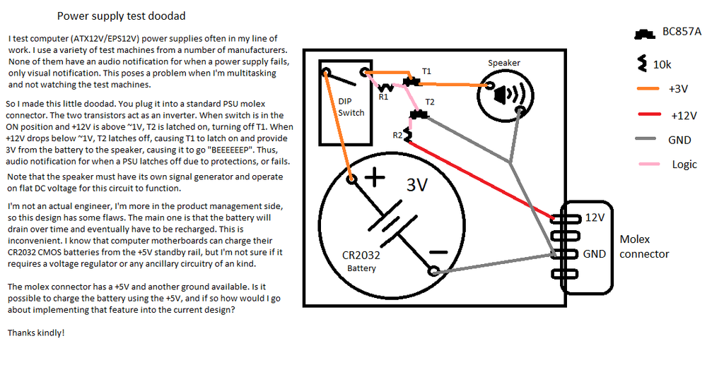
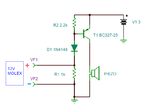
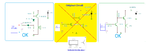
The original test circuit checks and latches a dropout condition on 12V only
 Teach me to be more careful with model #s! I just asked one of our engineers to give me some parts that would work and he gave them to me (he also pointed out a mistake that would have rendered it inoperative ). I'll be back in the office tomorrow briefly, I'll grab the real # then. The circuit does in fact work, except that I don't have a speaker that will work in it. XD All we have are old motherboard speakers and they all require a modulated signal, not just flat DC. However I tested with a DMM and it shows voltage across the speaker when it's supposed to, and doesn't when it isn't supposed to. So it works. Only time I should have "false" trigger is when in standby mode, since I'm not monitoring +5VSB. But a beep during the brief standby tests shouldn't bug me. You can always ask ... You can always ask ... on facebook ha.. https://www.facebook.com/evver
choose 9~24Vdc or so piezo device not a magnetic speaker.
When +12V fail condition is detected the speaker will draw current from the battery and after a while the battery will be drained. :roll:I do not recommend charging any type of lithium battery, sometimes those may explode… And what’s the point for charging if we get a zero stand-by current circuit? :roll:
Yes, you may add supplementary monitoring LED’s to any of the +5V/+12V using series limiter resistor( 1k to 2.2k).
gotcha no direct tech support. Got Service manuals ? I imagined you were testing many in parallel. Not one at a time.