Continue to Site

Welcome to EDAboard.com

Welcome to our site! EDAboard.com is an international Electronics Discussion Forum focused on EDA software, circuits, schematics, books, theory, papers, asic, pld, 8051, DSP, Network, RF, Analog Design, PCB, Service Manuals... and a whole lot more! To participate you need to register. Registration is free. Click here to register now.

[SOLVED] Matching line level audio to tape deck head amp.

Status
Not open for further replies.

LISA_DALTON

Junior Member level 3
Joined
Jan 31, 2012
Messages
27
Helped
5
Reputation
10
Reaction score
5
Trophy points
1,283
Location
CA.
Activity points
1,516
Hello, all fellow geeks!
I am setting up a tape deck head input to a iPod line level output.
1VPP I believe. What was being used was a phony cassette, with the inductive
transfer coil, which presses against the head, creating a signal transfer transformer.

I want to go from iPod to head input (head disconnected), via a simple voltage divider for right an left channels.
My question is, what value resistors should I use to create the ratio to drop the signal level
from the 1VPP iPod output down to the approximate 5mV the head actually puts out normally, with tape.

I guess it would be called an impedance matching issue. I would think the head Z to be low,
but the head amp input to be high, so as to not load down the tiny, and low power head signal.

Thanks,
-Lisa
:p
 

It sounds like you need to reduce the voltage by a factor of about 100. I would use 10K and 100 Ohms. 10K is high enough to be an easy load for the iPod and 100 Ohms is low enough to not introduce too much noise.

There might be a bit of a problem with the sound quality if the preamplifier in the tape deck has frequency response correction. You could probably fix that with a capacitor across one of the resistors though.
 
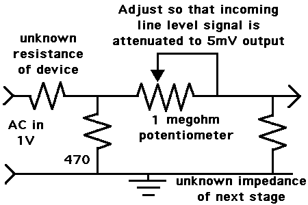
The schematic below shows the general idea. The adjustable potentiometer is what you really need, since you don't know the precise impedances. The 470 resistor is included to provide an output path for your iPod, and is not a crucial value.

You may get increased hum, depending on how well things are shielded.

This layout may or may not affect frequency response. The tape head amplifier may use an RIAA curve.

Not sure if the tape head amplifier is designed to expect a low impedance in the previous stage (the tape head).

25_1335430268.gif
 
Not sure if the tape head amplifier is designed to expect a low impedance in the previous stage (the tape head).
Yes, it will want to be driven by a low impedance to minimize noise.

I was thinking of a much simpler circuit:

 
Lisa, what kind of "tape deck" is this? If it's something like an old ghetto blaster, music center or car radio/tape, there's probably a much better way to do this.

The idea is to bypass the tape head preamplifier completely and feed the signal from the iPad directly (with no attenuation) into a part of the circuit that wants a line level signal. This isn't too hard.

Plan A is to aim for the volume control potentiometer. Disconnect the input to it from whatever it's connected to, and feed in the iPad signal there. If the "tape deck" has other sources (e.g. radio or CD) that you still want to use, you can drill an extra hole in the front panel and add a switch that lets you switch the input to the volume control between iPad and normal. In a similar conversion I did ages ago, I hijacked the "mono" switch (which was never used anyway), and repurposed that to switch the new input. (That was to add a CD input to an ancient receiver).

Plan B is to aim for the source selector switch. Then disconnect the "tape" switch contacts from whatever they're connected to, and connect them to the iPad signal instead. That way you can't use the tape anymore, but it sounds like you weren't planning to anyway.

Cheers - Godfrey
 

Godfrey,
I was having a blonde moment when I wrote the original post.
I am modifying a motorcycle sound system, so their iPod can blg in for power and sound.
Their previous set-up used a cassette deck head transfer system.
Because it has no crossover switch, (play only), it makes it only slightly tougher to find a good
spot to connect to.
I have however ruled out the head wires as an option for the input
Also the volume pot is not an option, as it also controls the radio built in to the cycles system.
I doubt I can find a schematic, but I'm sure i could find both the inputs and outputs of the head amp.
What about cutting the head amp output at the IC, then solder the ipod's L & R outputs to those traces.
I would still need to make a voltage divider, but the signal should be high enough where noise should not be an issue. The head input was just a bad idea.
Thanks for your input!
-Lisa
be into
 

Also the volume pot is not an option, as it also controls the radio built in to the cycles system.

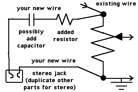
There's a chance you will not need to disconnect it. Perhaps just connect the new wires to the pot, at the correct terminal once you have located it. Then when you want to listen to the iPod, you will set the source switch to any position other than radio.

It's still a good idea to insert some series resistance for the iPod signal. What value should it be? Not so high that it seriously impedes volume.

Possibly also a decoupling capacitor if you like to be on the safe side (although I probably would not bother if it were me, since it can reduce bass volume).

Per this schematic...

56_1335683559.gif
 

BradtheRad,
I going to put my scope on the signal, to see if there is a DC offset. If not, I won't use any cap for best frequency response.
Thanks,
_Lisa
 

Status
Not open for further replies.

Similar threads

Part and Inventory Search

Welcome to EDABoard.com

Sponsor

Back
Top