Vermes
Advanced Member level 4
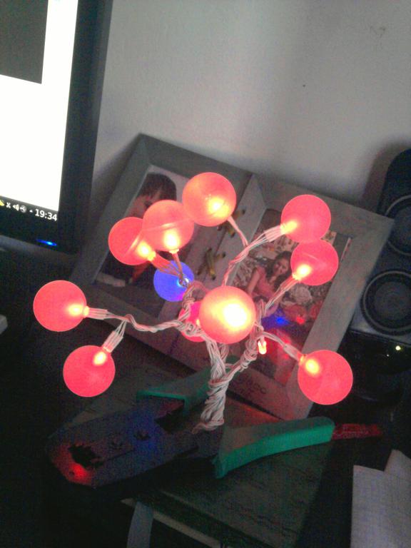
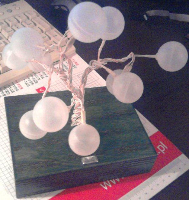
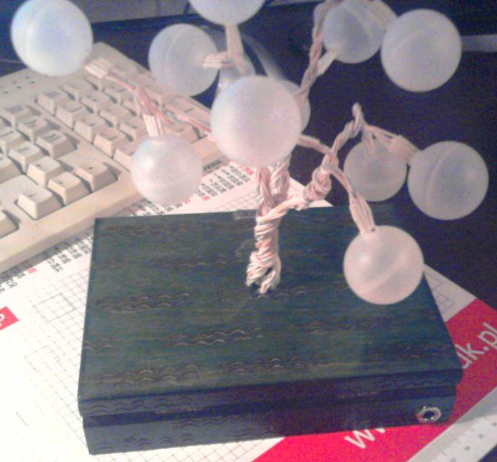
Leaves of that tree of happiness are made of RGB LEDs. Light is scattered thanks to deodorant balls used. Branches were made of computer twisted-pair cable. A box with whole electronics serves as a stand. In addition, there is an electet microphone in the trunk, which is used when the tree operates in the mode of sound spectrum analyzer (light colour of each LED corresponds to the intensity of a certain frequency of sound).
The tree has different modes of lighting, switched by a touch button in the base:
- constant change of colours of individual branches
- sound spectrum analyzer
- continuous illumination of the selected colour
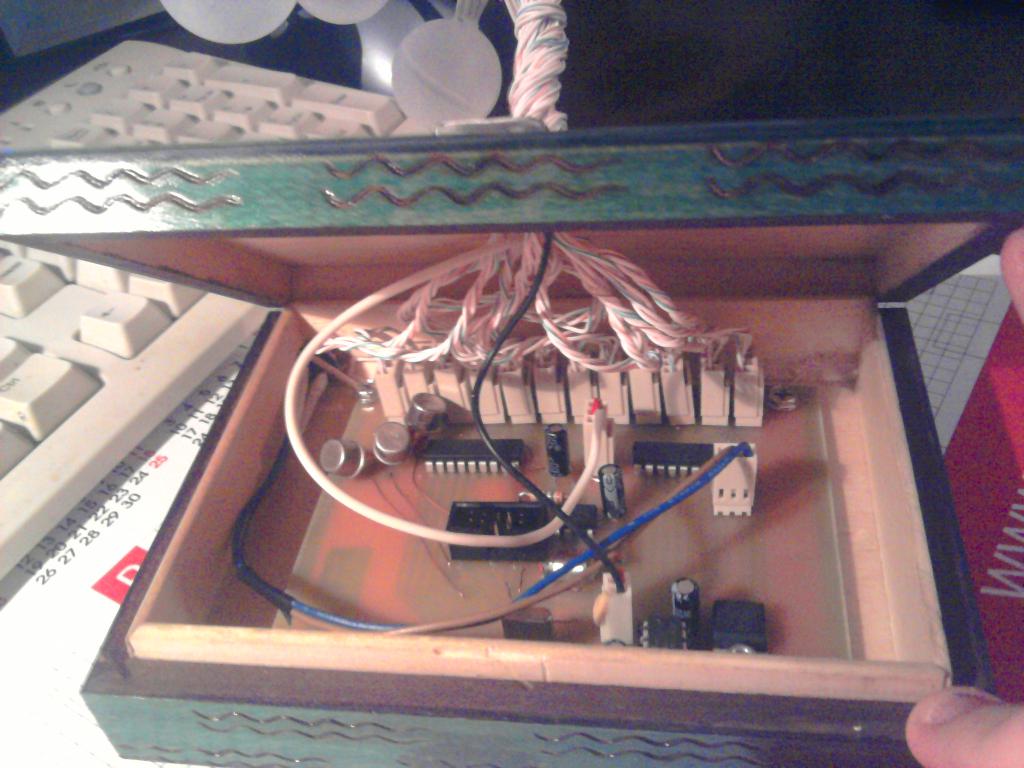
The main element of the system controlling the operation of the tree is processor AVR Atmega8. It is clocked by an external quartz 14.745MHz. 12 + 3 processor outputs were used for the control of 12 LEDs (1 output for the colour and 1 of LED selection). LEDs are lit one after another with such a high frequency, so they seem to light continuously. LEDs are connected to the processor from the side of power supply through systems UDN2981A and NPN transistors from the side of the colour selection. Additionally, there is a microphone connected to the analog-digital converter input of the processor via operational amplifier LM358N. The touch button is used for changing the modes and based on NE555. The whole is powered from an external power supply via linear stabilizer 7805.
Schematic diagram:
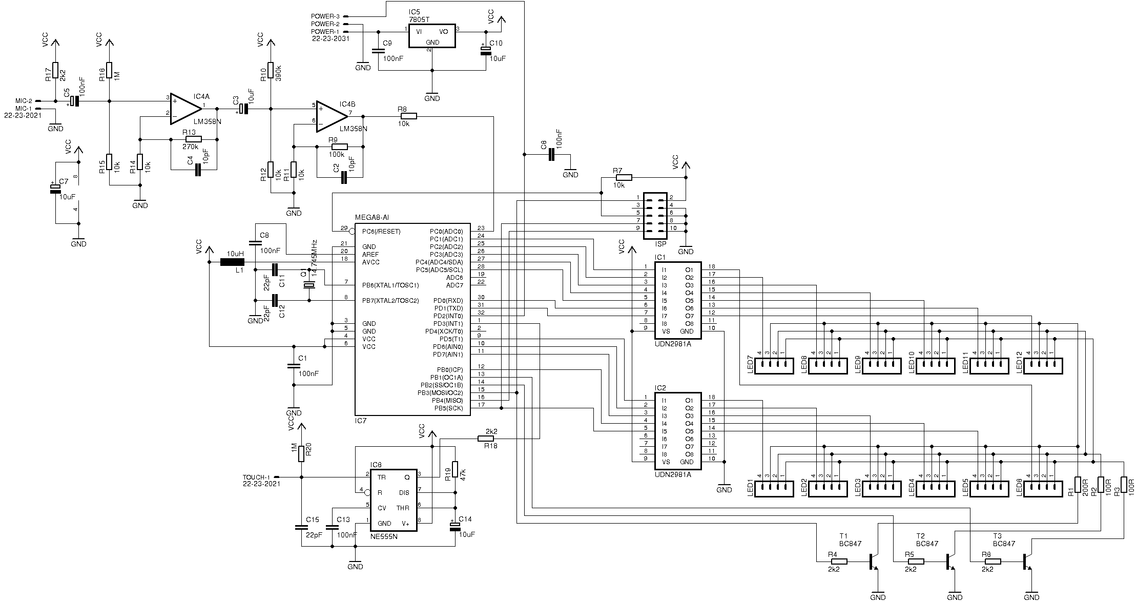
Software of the processor was written in C. Code in Assembler from avrfreaks was used for a fast fourier transformation (fft). LEDs are lit one after another in defined colour in TIMER0 interrupt. The frequency of LEDs change was experimentally selected.
Pictures:
Videos of operation in the sound spectrum analyzer mode:
Link to original thread (useful attachment) – Drzewko szczęścia led RGB