Continue to Site

Welcome to EDAboard.com

Welcome to our site! EDAboard.com is an international Electronics Discussion Forum focused on EDA software, circuits, schematics, books, theory, papers, asic, pld, 8051, DSP, Network, RF, Analog Design, PCB, Service Manuals... and a whole lot more! To participate you need to register. Registration is free. Click here to register now.

PIC16F877A Based Ammeter

Status
Not open for further replies.
Joined
Apr 8, 2012
Messages
201
Helped
3
Reputation
6
Reaction score
2
Trophy points
1,298
Activity points
0
Hello! I need a pic16f877A based circuit which can measure 0 - 100 Amps.


Thanks

internetuser2k11
 

Are you going to use a shunt or are you going to use other sensing methods such as magnetic or hall-effect sensor?
Have you done current sensing before? Do you know how it works?
 

Are you going to use a shunt or are you going to use other sensing methods such as magnetic or hall-effect sensor?
Have you done current sensing before? Do you know how it works?

No. I haven't done current sensing before. But I know that Current Transformers with op-amp circuits can be used to interface microcontrollers. What I need is a current sensing circuit interfaced to ADC pin of PIC16F877A.
 

Have you taken a look at any current transformer or hall-effect sensor?

Take a look at these:
**broken link removed**

Hope this helps.
Tahmid.
 

hello

But I know that Current Transformers with op-amp circuits can be used to interface microcontrollers. What I need is a current sensing circuit interfaced to ADC pin of PIC16F877A.

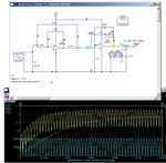
I fund a schematic of "Ideal rectifier with an Operatioanl Amplifier" and tested it with Circuit Maker Student CMS60.
If you use a 100/1 transformer, you will get 1Amp at the output when it is shorcut or with very low load at 100Amp on main AC.

Intensity Transformer is simulated to give 1Amp, on 5 ohms. ( because of generator 5V peak to peak!)
You must load the scondary of Intensity Transformer , else it wil burn out !
by a resistor of 5 or maybe 10 ohms to increase voltage output . 10W minimum !

You can see the results double alternance on V8
Signal is amplified and filtered by 22µF and RC of 10K & 10µF
Gain can be adjusted by R9
Check all to obtain near 5V for output and connect directly to ADC PIC input.
Zero offset can be remove by software !
You can use other AOP ..

Redresseur_Parfait_TI_LM358_ckt.jpg
 

Have you taken a look at any current transformer or hall-effect sensor?

Take a look at these:
**broken link removed**

Hope this helps.
Tahmid.

I won't be using hall effect sensors. What I need is a circuit consisting of current trf.
The primary of CT(current trf) will be connected in series with the phase or neutral of power line. Or it can also be connected to earthing wire to check earth leakage. An emf is induced in the secondary which is converted to dc (scaling down and isolation). Then two op-amp or 3 op-amp instrumentation amplifier is used to amplify the voltage which is fed to microcontroller ADC pin.
 

Status
Not open for further replies.

Similar threads

Part and Inventory Search

Welcome to EDABoard.com

Sponsor

Back
Top