Continue to Site

Welcome to EDAboard.com

Welcome to our site! EDAboard.com is an international Electronics Discussion Forum focused on EDA software, circuits, schematics, books, theory, papers, asic, pld, 8051, DSP, Network, RF, Analog Design, PCB, Service Manuals... and a whole lot more! To participate you need to register. Registration is free. Click here to register now.

stripline models for simulation?

Status
Not open for further replies.

ngox

Member level 2
Joined
Aug 4, 2011
Messages
50
Helped
0
Reputation
0
Reaction score
0
Trophy points
1,286
Activity points
1,718
I've been searching around for stripline model files for use in virtuoso, but I cannot find any good broadband ones. If anyone has any stripline model file that supports a maximally flat gain response up to 10GHz, it would be much appreciated. Dunno if this is the right section of the forum to post in.
 

Please explain in more detail what you are looking for.

Transmission lines, inclusing microstrip and stripline, are inherently broadband if the line impedance Zl=sqrt(L'/C') matches the input and output impedance at the end of the line. From your question, I would think that your problem is impedance matching/wrong transmission line impedance.
 

At the moment, I am trying to send a 10GHz signal through a stripline. When the length of the line is relatively short (an inch or less), there is no real problem. However, I would like to simulate for lengths of up to 6 inches. At this length, the line exhibits a flat magnitude response up to around 30MHz and then has harmonic spikes in the GHz range. I am relatively sure that the impedances are matched properly as I am currently using a field solver to calculate the matching impedances.

The frequency response of the stripline with no load or source impedances attached:
mtline_2.png

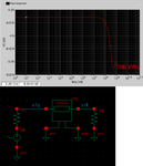
The frequency response with both 50ohm source and load resistors attached. This is the frequency of response of v1L only. The schematic is attached too.
mtline_3.png

For reference, the values I am using are
relative dielectric constant: 3
dielectric layer thickness 0.13mm
signal line width: 0.33mm
signal line thickness: 0.04mm
signal line spacing: 1mm
signal line conductivity: 576000000

The matched impedance should then follow to be 50 ohms.

I also used this to verifty if that helps: https://chemandy.com/calculators/microstrip-transmission-line-calculator-hartley27.htm
 
Last edited:

What is Y0 that you have plotted?

If it is transfer function/voltage ratio: The frequency response with both 50ohm source and load resistors looks more or less flat, with a minor drop (0.1dB) around 50MHz and then flat again. This does not look like a realistic line model.

What field solver have you used, and how did you create the input data/input file for the mtline model?
 

The Y0 I have plotted is the magnitude response with a 1V sine wave plotted with frequency.

In the mtline instance, I am choosing stripline, followed by field solver. I then input the length, fmax, relative dielectric constant, signal line width, signal line thickness, signal line spacing, and signal line conductivity.
For the moment I have chosen the lossless line option as well.

It looks like this: mtline_properties.png

There are RLGC, T-line, and S parameter options as well; however, I could not really find any models for those. Since this simulation is just for learning purposes, I am not too picky about what kind of model of stripline I use, so if you happen to have one available I would be grateful. Thanks.
 
Last edited:

Ok, I didn't realize that you are using the mtline model's built-in field solver. The use of the mtline model that I am familiar with is to take RLCG data calculated by an external field solver (Sonnet).

The line type that you have specified is microstrip (line above ground), not stripline (line with grounds above and below).

I simulated your line with "my" field solver (Sonnet). The line impedance that I get for your dimensions is 48 Ohm, which is close enough to your 50 ohm target value. From reflection and transmission values in my simulation, it can be seen that the line works perfectly fine up to 50GHz, as expected. At 10GHz, insertion loss is < 0.01dB/mm when simulated with metal loss, but ideal dielectric (er=3, tand=0).

My RLCG file is attached, just in case you want to try that.
 

Attachments

  • microstrip.zip
    24.1 KB · Views: 88

Thank you so much. It worked well. I presume that in the future I should extract the frequency dependent RLCG file and then import it into Cadence then.
 

Status
Not open for further replies.

Part and Inventory Search

Welcome to EDABoard.com

Sponsor

Back
Top