Continue to Site

Welcome to EDAboard.com

Welcome to our site! EDAboard.com is an international Electronics Discussion Forum focused on EDA software, circuits, schematics, books, theory, papers, asic, pld, 8051, DSP, Network, RF, Analog Design, PCB, Service Manuals... and a whole lot more! To participate you need to register. Registration is free. Click here to register now.

[MOVED] Tilt switch with an auto off feature

Status
Not open for further replies.

saabtech

Newbie level 4
Joined
Apr 20, 2012
Messages
5
Helped
0
Reputation
0
Reaction score
0
Trophy points
1,281
Activity points
1,316
i would like to power an led that is trigger with a tilt switch.

i would like it to power off with the tilt switch open or with the auto off timer. most everything i have found uses a 555ic but only uses a momentary switch as the reset. that will not due.

i have searched and search and i cant seem to put two and two together and put this circuit function.

thanks everyone.
i have made small circuits for fun before (its been 10 yrs) but i first started with a breadboard and enough componants to make the night rider sequence.

So you want a circuit which will turn off an LED if a tilt switch is open or after certain time period . Thats all? Or you want the LED will turn on again when the tilt switch is closed again?
 
So you want a circuit which will turn off an LED if a tilt switch is open or after certain time period . Thats all? Or you want the LED will turn on again when the tilt switch is closed again?

the tilt switch needs to be the trigger "on" when closed for the LED.
if the tilt switch is left on the LED needs to auto off after about 2-3 min.
if the tilt switch is opened the LED will go off, and will come back on with the tilt switch closed trigger.

thanks.
 

Use the following circuit with the changes mentioned:-

alarm-timer.gif


Components values
R1 = 2.2MΩ
R2 = 18kΩ
R3 = R5 = 1kΩ
R4 = 1MΩ
C2 = 10nF
T1 = BC557 [Circuit shows a NPN transistor. Replace that NPN with BC557 PNP as describe below]
IC1 = CD4060


1. In place of s1, connect the Tilt switch.
2. 1 to 120 minutes delay use : C1=470nF; P1=1MΩ . adjust P1.
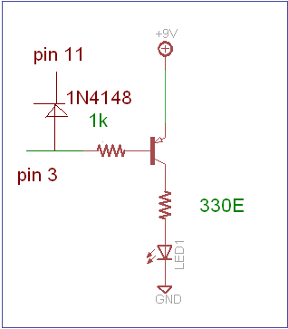
3. In place of the NPN transistor and buzzer use the following connection:-

85_1334969266.png


---------- Post added at 06:19 ---------- Previous post was at 06:18 ----------

You can remove D1 and R3
 
i would like to use two 1.5v batteries (3v) would that change the values or function of these circuits?
thanks again for the quick responces.

and a question about the 1n4148 taveling to pin 11, is that before r1 (away from the ic) or after (closer to the ic)
 
Last edited:

No as it is a CMOS IC, You can easily use 3V. Power consumption is very very low. In that case you may have to lower the 330 ohm resistance to obtain desired brightness.

And or the diode. One end of 1N4148 will be connected to pin 11 after R1(close to IC). That is one end of R1 and one end of 1N4148 both will be connected to pin 3. 1N4148 is used to prevent the CD4060 to act as repeating timer. 1N4148 stops the count by disabling the oscillator when pin 3 is high. When pin 3 is high the PNP transistor switch goes off and the connected LED goes off too.
 
you're very kind. this will keep me entertained for serveral days, i will try to update you one the project.
thank you very much.
 

the circuit is made on the breadboard and functions as designed. i have changed the capacitors and resistors to lower the time spand to a 1 -3 min adjustemt instead of 1-120 min. now im thinking i could integrate a dusk/dawn sensor into it and have a light dependent option.
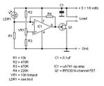
would something like this be needed or is there a better option.schemati.gif
 

Yes. Its good to use a voltage comparator (op amp, like IC741 based) with LDR to make a dark/dawn sensor.
You can search google, there are some very interesting tutorials on voltage comparator.
 
Status
Not open for further replies.

Similar threads

Part and Inventory Search

Welcome to EDABoard.com

Sponsor

Back
Top