Continue to Site

Welcome to EDAboard.com

Welcome to our site! EDAboard.com is an international Electronics Discussion Forum focused on EDA software, circuits, schematics, books, theory, papers, asic, pld, 8051, DSP, Network, RF, Analog Design, PCB, Service Manuals... and a whole lot more! To participate you need to register. Registration is free. Click here to register now.

amps from dual rail circuit?

Status
Not open for further replies.

qweets

Junior Member level 2
Joined
Dec 18, 2010
Messages
21
Helped
1
Reputation
2
Reaction score
1
Trophy points
1,283
Activity points
1,447
hello : )

i have a 12v regulator that can haddle 1.5 amps. i made a dual rail power circuit so that i can power a number of op amps and alike from it. but i am not sure of the power limitations of the dual rail circuit? would this depend on the caps and resistors used? The resistors used in the dual rail supply circuit are 4.7k @ .6 watt and the caps are 470uf @ 35v.

would this dual rail be able to supply 1.5 amps from the 12v regulator?

thanks for any help.

here is a pic:
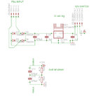
dual rail q.jpg
 

Sorry, but that's not going to work. You can't just make a dual rail supply by using a potential divider, not a usable one anyway. Imagine if one side draws more current - the centre voltage changes.

It looks like your transformer input has two sets of 15V windings. If so, connect them to get 15-0-15 volts (the end of the first winding connects to the start of the second winding to give the centre zero. Then, use an additional regulator (-12V, like a 7905) on the negative side. Something like this:

drps.jpg
 

hi, thanks foxyrick, i really like the idea behind a dual regulator circuit.

sorry but i have given misleading info on the external psu input. My external psu reads approx 15v with no load on it. ( attaching my multimeter to it) and the 4 pins are simply a 4 pin molex port/header ( i use 4 pins instead of 2 because the 4 pin molex connector is more sturdy and less likely to fall off, than the 2 pin version. i should have mentioned, or left that out. The psu is not all that special, its just a psu off an old HP printer with a sheild and a single core (+) , so just the two connections.

is there a way to use a dual regualtor circuit from such a psu?

: )
 

Is your HP power supply DC or AC? If it is already DC, then you don't need the rectifying diodes (D1-D4) and can connect straight to the first capacitor instead. Just make sure to connect + and - the correct way around.

As to creating the negative, it can be done but not quite as simply as the positive regulator side. You would need to use an inverting, switching regulator. About the simplest (and a good one) is the MC34167 from OnSemi, although there are many others. See page 12 in the datasheet (second link) for the circuit. this is just for the negative side - you would build the positive regulator as above, then connect your +12V to the Vin(12V) in the datasheet to get the negative output.

https://www.onsemi.com/PowerSolutions....do?id=MC34167
https://www.onsemi.com/pub/Collateral/MC34167-D.PDF

It would be easier if you could get another PSU or transformer, and wire the negative of the first to the positive of the second. That way you will get the +15, 0, -15 to feed to the regulator circuit in my first post. Just make sure that the PSU's are the type that are not connected to the mains ground/Earth, i.e. they only have two mains wires, not three, otherwise you can't wire them up like that, something will melt! If you can get one, ask if you want more advice on this.

A couple of extra tips:

The 78xx series of regulators need at least about 2V more input than output, so 15V is a good choice to give a 12V output but not much less.

You might be surprised how hot the regulators get if you draw even a few hundred mA from them, and if you get up to an amp or so, really hot! You will need to use a heatsink. If your regulators/heatsink get so hot that you really don't want to keep your fingers on it, you need a bigger heatsink.
 
  • Like
Reactions: IanP

    IanP

    Points: 2
    Helpful Answer Positive Rating

Attachments

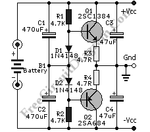
  • Virtual-Ground-Circuit-1-Discrete.gif
    Virtual-Ground-Circuit-1-Discrete.gif
    7.4 KB · Views: 102

Status
Not open for further replies.

Similar threads

Part and Inventory Search

Welcome to EDABoard.com

Sponsor

Back
Top